Multi-section filamentary endoluminal stent

a filamentary endoluminal and stent technology, applied in the field of endoluminal stents, grafts,/or prostheses, can solve the problems of incomplete sealing or migration of the device after the stent, insufficient radial strength, and insufficient radial strength, so as to reduce the radial strength

a filamentary endoluminal and stent technology, applied in the field of endoluminal stents, grafts,/or prostheses, can solve the problems of incomplete sealing or migration of the device after the stent, insufficient radial strength, and insufficient radial strength, so as to reduce the radial strength

US7160319B2Inactive Publication Date: 2007-01-09LIFESHIELD SCI

Image

  • Multi-section filamentary endoluminal stent
  • Multi-section filamentary endoluminal stent
  • Multi-section filamentary endoluminal stent

Examples


Embodiment Construction

[0043]The invention will next be illustrated with reference to the figures wherein similar numbers indicate the same elements in all figures. Such figures are intended to be illustrative rather than limiting and are included herewith to facilitate the explanation of the apparatus of the present invention.

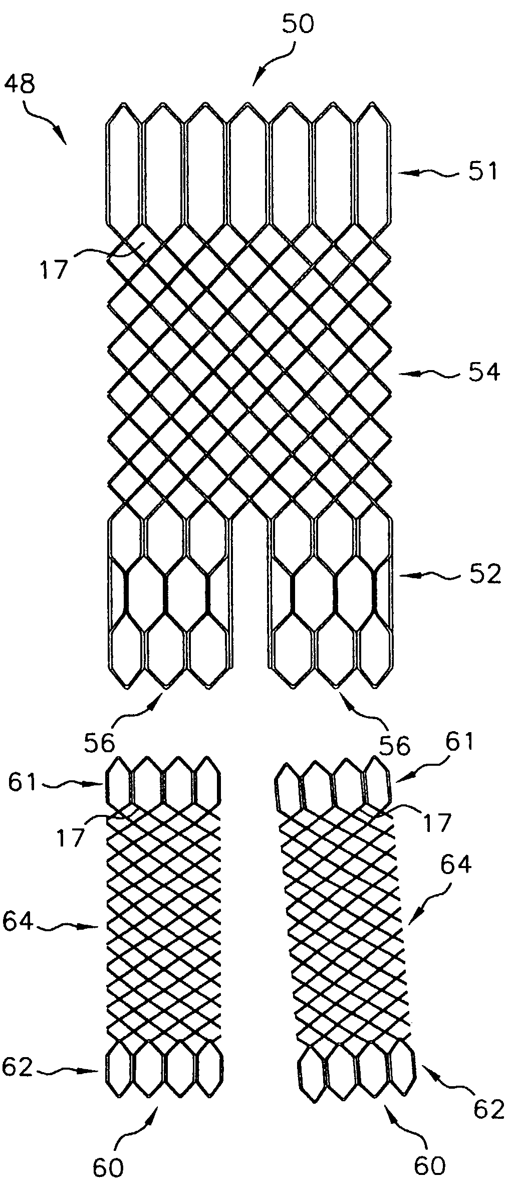
[0044]FIG. 3 shows an exemplary stent embodiment according to the present invention wherein the tubular stent has been cut along a line parallel to the tubular stent axis and flattened. As shown in FIG. 3, stent 10 comprises two end sections 12 and a middle section 14. Middle section 14 has a first stent architecture that comprises a braided stent such as is described in U.S. Pat. No. 4,655,771 to Hans I. Wallsten, and incorporated herein by reference, and end sections 12 have a second stent architecture that comprises a wound stent. End sections 12 have a wound stent architecture comprising one or more filaments in a repeating configuration having at least one bent portion. As show...


PUM


Abstract

A multi-section filamentary stent comprises a braided section, which is a cylindrical mesh of a first set of filaments, connected to at least one wound section comprising a second set of one or more filaments having a repeating configuration with a bent portion. The two sections are preferably connected by at least one continuous filament extending into both sections. The two sections may be connected by a weld, a suture, a common graft, an overlapping portion of the two sections, or one or more filaments of one section looping through portions of the other section. The stent may comprise a first section, having a braided first stent architecture with a first flexibility and a first radial force, and a second section, having a non-braided second stent architecture with a second flexibility less than the first flexibility and a second radial force greater than the first radial force, in which at least one continuous filament is integral to both the first and second sections. The stent may have a radially compressed configuration and a radially expanded configuration, in which the first section has a first shortening ratio, and the second section has a second shortening ratio less than the first shortening ratio. Such multi-section stents may comprise modular components of a modular stent, such as a bifurcated modular stent, adapted for joining together in situ. The multi-section stent may comprise a first section having a first percentage of open area and a second section having a second percentage of open area. The stent may also comprise a first section having a first stent architecture with an end effect wherein the radial strength at the end is less than elsewhere in the stent, and a second section having a second stent architecture to counteract the end effect. Methods for treating body lumen by implanting the stents as described herein are also disclosed, as is a method for counteracting a stent architecture end effect.

Description

CROSS-REFERENCE TO RELATED APPLICATIONS[0001]The application is a divisional of U.S. application Ser. No. 09 / 442,165 Nov. 16, 1999, now U.S. Pat. No. 6.585,758.TECHNICAL FIELD[0002]This invention relates generally to endoluminal stents, grafts, and / or prostheses and, more specifically, to stents having multiple longitudinal sections of different stent architecture.BACKGROUND OF THE INVENTION[0003]A stent is an elongated device used to support an intraluminal wall. In the case of a stenosis, a stent provides an unobstructed conduit for blood in the area of the stenosis. Such a stent may also have a prosthetic graft layer of fabric or covering lining the inside or outside thereof, such a covered stent being commonly referred to in the art as an intraluminal prosthesis, an endoluminal or endovascular graft (EVG), or a stent-graft.[0004]A prosthesis may be used, for example, to treat a vascular aneurysm by removing the pressure on a weakened part of an artery so as to reduce the risk of...

Claims


Application Information

Patent Timeline
09 Jan 2007
Publication
US7160319B2
IPC
A61F2/06; A61M29/00; A61F2/00; A61F2/82; A61F2/90
CPC
A61F2/91; D04C1/06; A61F2/90; A61F2/07; A61F2230/0054; A61F2/915; A61F2002/065; A61F2002/067
Inventors
CHOUINARD, PAUL F.; HAVERKOST, PATRICK A.