
Voltage/current testing equipment for microfluidic devices

a technology of voltage/current testing and microfluidic devices, which is applied in the direction of instruments, separation processes, glassware laboratories, etc., can solve the problems of affecting the accuracy of microfluidic devices

Active Publication Date: 2007-01-09
CAPLIPER LIFE SCI INC
View PDF51 Cites 128 Cited by
  • Summary
  • Abstract
  • Description
  • Claims
  • Application Information

AI Technical Summary

Benefits of technology

"The present invention provides methods, systems, and devices for testing and verifying the proper function of microfluidic elements in a microfluidic device. These methods involve setting known voltages or currents in the device and detecting the resulting voltage or current at different fluidic openings. The detected values are then compared to calculated target values to determine if there is a fault in the device. The testing process can be repeated at other fluidic openings to ensure proper functioning of all microscale channel elements. The invention allows for the efficient and accurate testing of microfluidic devices, which can aid in the development and manufacture of such devices."

Problems solved by technology

Additionally, mistakes in construction of the microfluidic device (e.g., mistakes in etching or milling) can possibly produce a blocked, misaligned, or mispatterned microelement.
However, with complex microfluidic element arrangements, it can be difficult to accurately assess each element in the microfluidic device.

Method used


Image

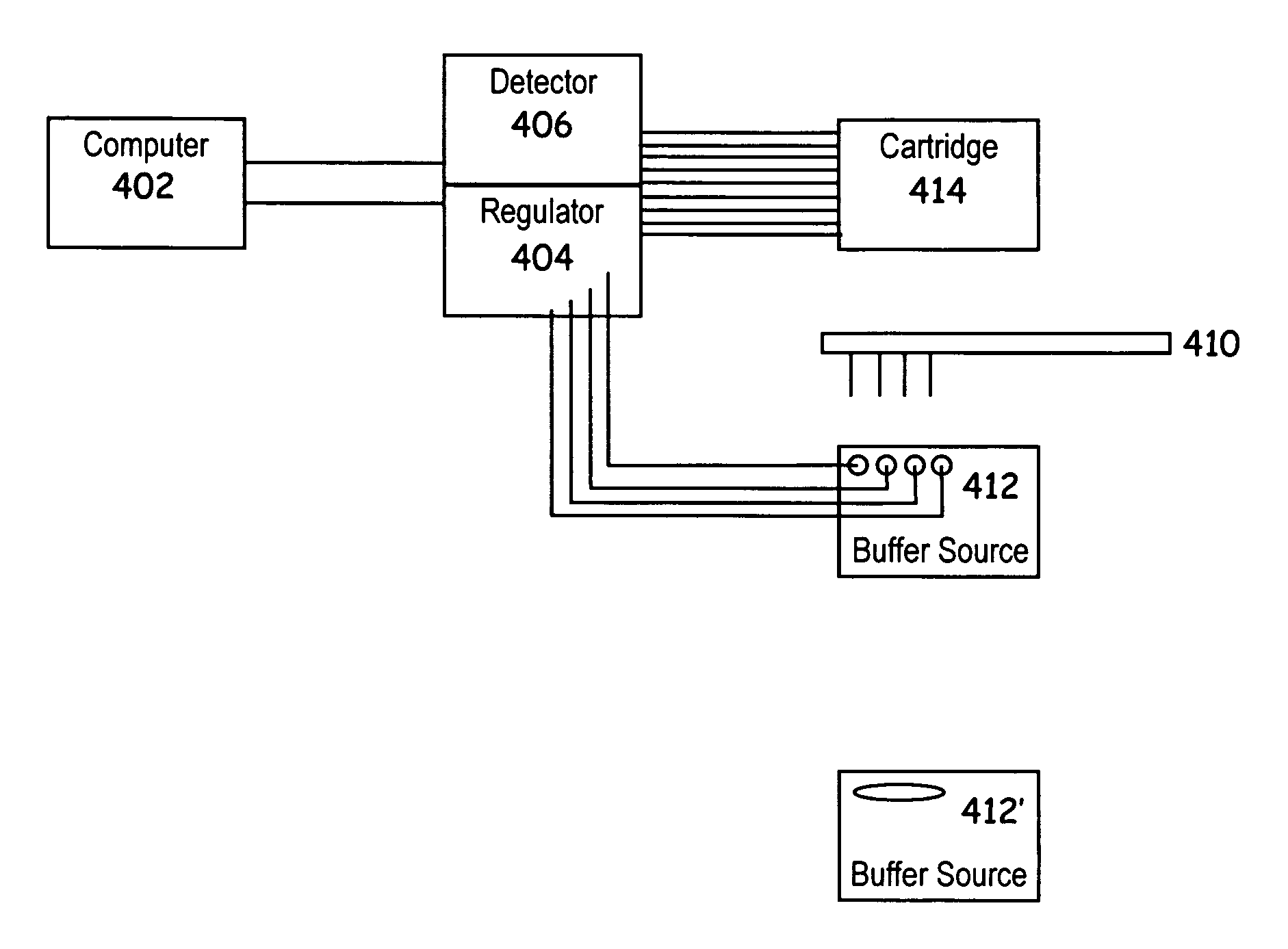
  • Voltage/current testing equipment for microfluidic devices
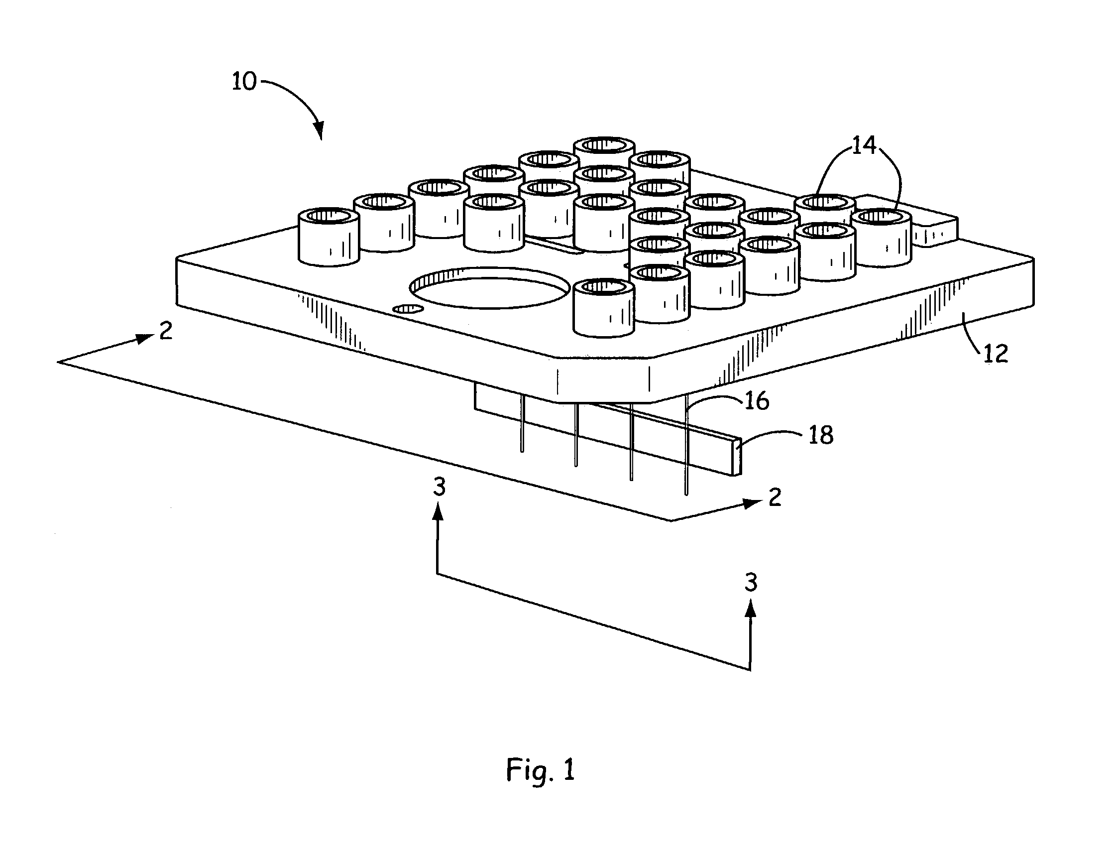
  • Voltage/current testing equipment for microfluidic devices
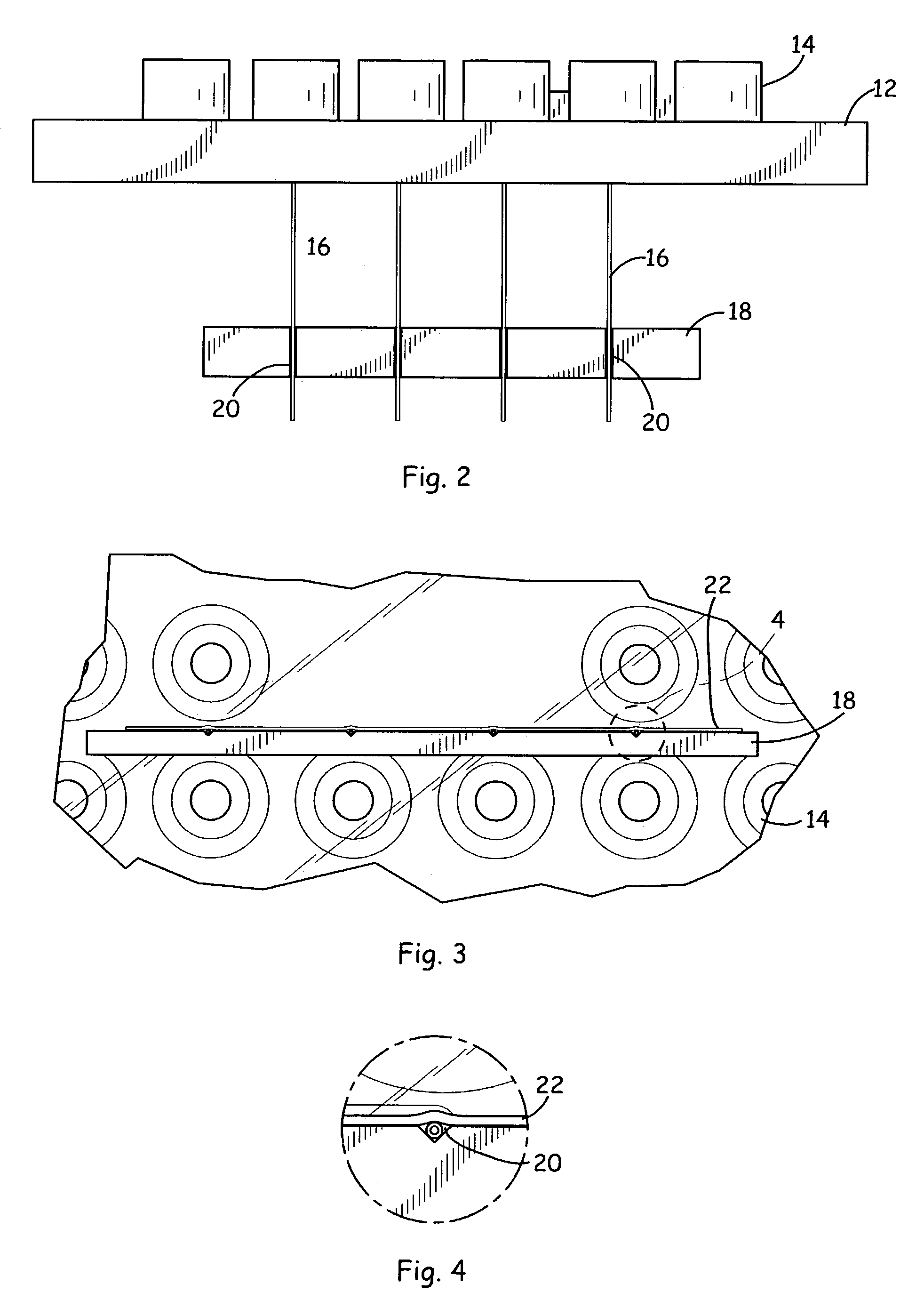
  • Voltage/current testing equipment for microfluidic devices

Examples


Embodiment Construction

[0023]The methods and devices of the invention directly address and solve concerns associated with testing the proper function of microfluidic channels and devices. Specifically, the invention provides methods for determining whether the various microfluidic channel or capillary elements in a microfluidic device are blocked (e.g., by incomplete etching of a microchannel, presence of an air bubble, etc.).

[0024]Briefly, the methods and devices of the current invention involve the testing of microfluidic devices in order to detect bubbles trapped within the microfluidic channels and / or blocked elements, misplaced patterns of elements, etc. As explained in more detail below, devices herein set known voltages and / or currents at two or more various fluidic openings (e.g., open wells or reservoirs at the ends of microchannels, fluidic openings at the ends of capillary elements, etc.) of microfluidic devices. The resulting voltages / currents measured at a third fluidic opening which is fluid...


PUM

PropertyMeasurementUnit
widthaaaaaaaaaa
widthaaaaaaaaaa
pHaaaaaaaaaa

Abstract

The present invention provides novel methods and devices for testing / verifying the configuration of one or more microfluidic elements in a microfluidic device. In particular the methods and devices of the invention are useful in testing for blockages or the presence of air bubbles in microfluidic elements. For example, a method for verifying the proper function of a microfluidic device is disclosed, which device comprises at least first, second and third fluidic openings, which fluidic openings are fluidly coupled to at least first, second and third microscale channel elements, respectively, the method comprising flowing an electrically conductive buffer through the first, second and third microscale channel elements; setting a known applied voltage potential (or current) between the first and second fluidic openings; setting a current in the third microscale channel element to be approximately zero; detecting a resulting voltage at the third fluidic opening; and, comparing the detected voltage at the third fluidic opening with a calculated target voltage expected at the third fluidic opening to determine whether there is a fault or problem (e.g., air bubble) in at least one of the first and second microscale channel elements. The above method can be repeated one or more times for the other fluidic openings in the microfluidic device to determine whether there is a fault in any one or more microscale elements of the device.

Description

CROSS-REFERENCE TO RELATED APPLICATION[0001]This application claims the benefit of U.S. Provisional Patent Application No. 60 / 386,038, filed Jun. 5, 2002, which is incorporated herein by reference in its entirety for all purposes.BACKGROUND OF THE INVENTION[0002]The performance of chemical or biochemical analyses, assays, or preparations often requires a large number of separate manipulations to be performed on the materials or components to be assayed, including measuring, aliquotting, transferring, diluting, mixing, separating, detecting, incubating, etc. Microfluidic technology miniaturizes these manipulations and integrates them so that they can be executed within one or a few microfluidic devices. For example, pioneering microfluidic methods of performing biological assays in microfluidic systems have been developed, such as those described by Parce et al., “High Throughput Screening Assay Systems in Microscale Fluidic Devices,” U.S. Pat. No. 5,942,443 and Knapp et al., “Closed...

Claims


Application Information

Patent Timeline
Patent Type & Authority Patents(United States)
IPC IPC(8): G01R31/08G01N27/00
CPCB01L3/5027B01L2200/143B01L2200/148B01L2400/0487B01L2400/0418B01L2400/0421B01L2300/0816
Inventor CHIEN, RING-LING
Owner CAPLIPER LIFE SCI INC
Learn More