Electroluminescent lamp module and processing method

a technology of electroluminescent lamps and processing methods, which is applied in the direction of discharge tubes luminescnet screens, printed circuit non-printed electric components association, instruments, etc., can solve the problems of increased cracking chances, increased electrical frequency, and easy cracking of the dielectric layer, and achieves high speed, easy manufacturing, and large volume production

Inactive Publication Date: 2005-07-26
MORGAN ADHESIVES COMPANY
View PDF58 Cites 10 Cited by
  • Summary
  • Abstract
  • Description
  • Claims
  • Application Information

AI Technical Summary

Benefits of technology

[0010]The present invention is an EL lamp module and a method of producing an EL lamp module. The EL lamp module provides both an EL lamp (attachable or printed) and electrical components for the proper function of the EL lamp in a single structure, thereby eliminating the necessity of separate electrical and mechanical connections for the final application of an EL lamp. The EL lamp module includes a printed circuit pattern and printed electrical components, and / or electrical components that may be connected through conventional printing techniques utilizing conductive and / or non-conductive pressure sensitive adhesives. The EL lamp may be printed using conventional screen printing techniques contemporaneously with the printing of the circuit pattern and application of electrical components, or in another embodiment, an EL lamp label such as those disclosed in pending application Ser. No. 09 / 742,490 can be pre-manufactured and applied to a base substrate of an EL module. EL labels can be easily manufactured in large quantities on a continuous release liner provided in a roll or reel form in both unidirectional light-emitting and multi-directional light-emitting forms. Thus, the present EL module is complete with required circuitry and can be manufactured in large volumes and at high speeds using commercial printing, drying, laminating, punching and blanking equipment.

Problems solved by technology

On the other hand, the dielectric layer is prone to cracking when multiple layers are printed one over the other.
Also, the chances of cracking are increased when the dielectric layer becomes too thick.
However, if increased brightness is required, then additional electronics may be required to increase the electrical frequency of the current for the lamp.
Unfortunately, when the operating voltage and / or frequency of an EL lamp are increased, the life of the EL lamp may decrease more rapidly.
This increases manufacturing cycle times and increases the probability of the occurrence of manufacturing defects by utilizing separate electrical and mechanical connections in the EL lamp design.

Method used


Image

  • Electroluminescent lamp module and processing method
  • Electroluminescent lamp module and processing method
  • Electroluminescent lamp module and processing method

Examples


Embodiment Construction

[0024]While the present invention will be described fully hereinafter with reference to the accompanying drawings, in which a particular embodiment is shown, it is to be understood at the outset that persons skilled in the art may modify the invention herein described while still achieving the desired result of this invention. Accordingly, the description that follows is to be understood as a broad informative disclosure directed to persons skilled in the appropriate art and not as limitations of the present invention.

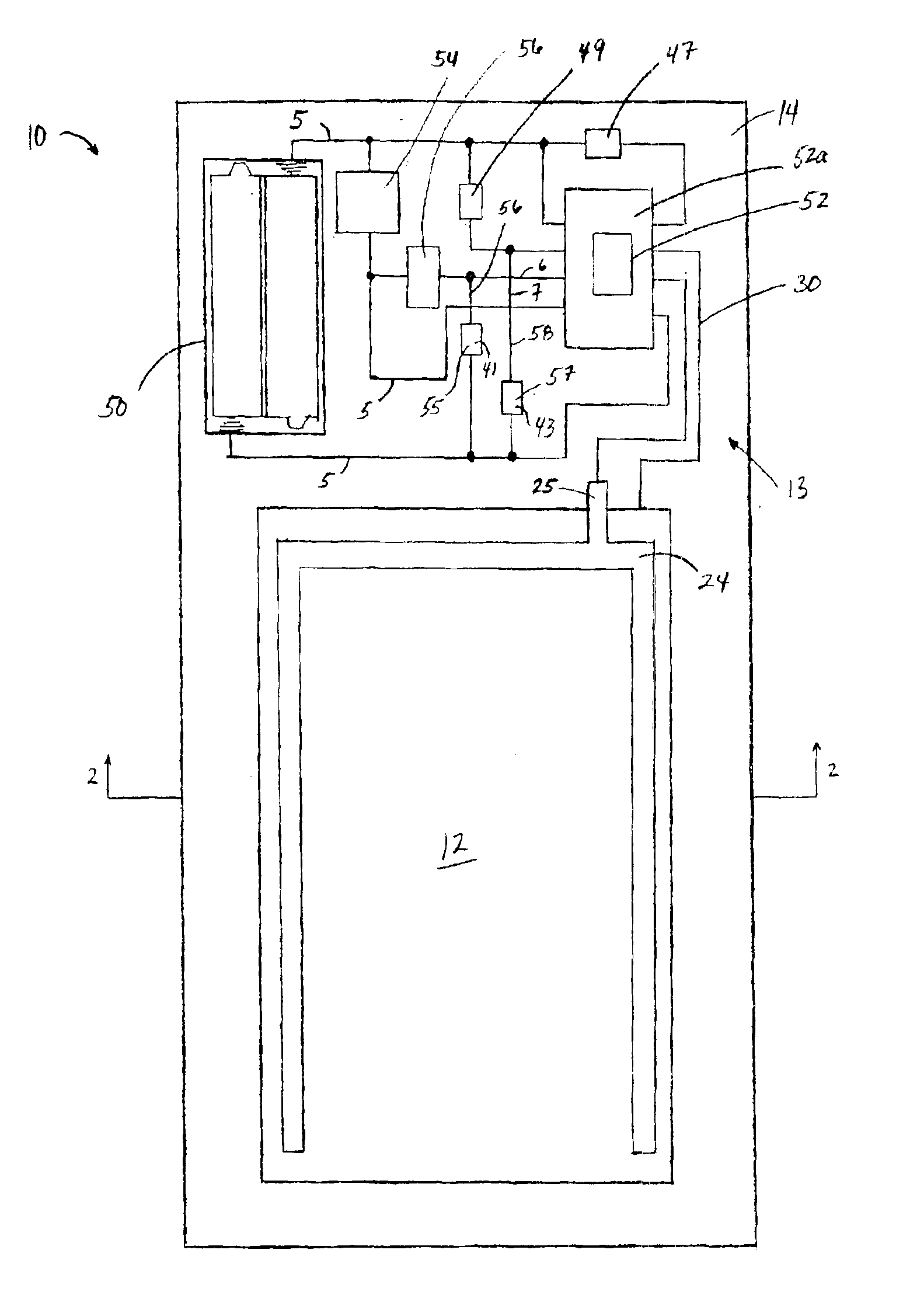
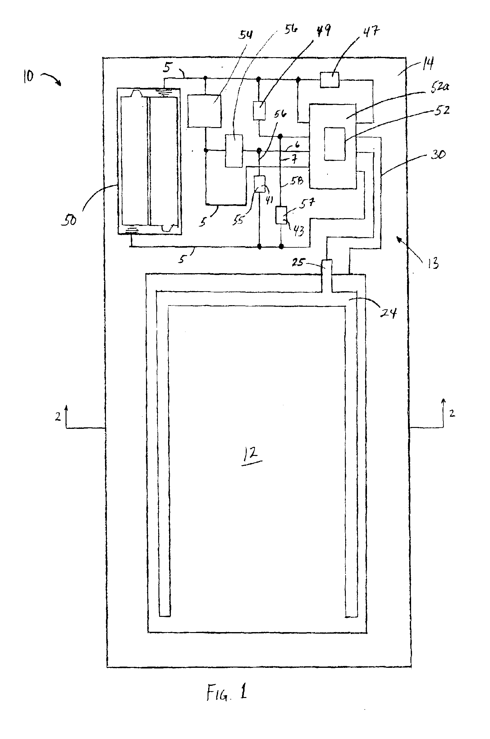
[0025]FIG. 1 shows an EL lamp module 10 that includes a unidirectional EL lamp 12 and an EL lamp circuit 13. The EL lamp circuit 13 includes the necessary electrical components required for the desired operation characteristics of the EL lamp 12 and a circuit pattern 30 that operates as the electrical connection or electrical leads 5 between any included electrical components. As shown in FIG. 1, the EL lamp circuit 13 and EL lamp 12 are on the same side of the base su...


PUM


Abstract

The present invention is an EL lamp module and a method of producing an EL lamp module. The EL lamp module of the present invention provides both an EL lamp (attachable or printed) and required electrical components for the proper function of the EL lamp in a single structure, thereby eliminating the necessity of separate electrical and mechanical connections for the final application of an EL lamp. The EL lamp module includes a printed circuit pattern and printed electrical components, and/or electrical components that may be connected through conventional printing techniques utilizing conductive and non-conductive pressure sensitive adhesives.

Description

BACKGROUND OF THE INVENTION[0001]The present invention relates to electroluminescent (EL) lamp modules and a method of making EL lamp modules. More particularly, an EL lamp module includes an EL lamp and a pre-printed circuit pattern that includes an EL driver and other electronic components that are printed and / or mechanically and electrically attached to the circuit pattern, by means of conductive and / or non-conductive pressure sensitive adhesives (PSA).[0002]EL lamps are basically devices that convert electrical energy into light. AC current is passed between two electrodes insulated from each other and having a phosphorous material placed therebetween. Electrons in the phosphorous material are excited to a higher energy level by an electric field created between the two electrodes during the first quarter cycle of the AC voltage. During the second quarter cycle of the AC voltage, the applied field again approaches zero. This causes the electrons to return to their normal unexcit...

Claims


Application Information

Patent Timeline
Patent Type & Authority Patents(United States)
IPC IPC(8): H05B33/02H05B33/08H05K3/32H05K1/18H05B44/00
CPCH05B33/08H05K1/181H05K3/321Y02B20/325Y02B20/30H05B44/00
Inventor PENNAZ, THOMAS J.TUCHOLSKI, GARY R.
Owner MORGAN ADHESIVES COMPANY
Why Eureka
Try Eureka