Demountable drive mechanism

a drive mechanism and drive shaft technology, applied in the direction of loading/unloading vehicle arrangment, vehicle maintenance, transportation items, etc., can solve the problems of cumbersome prior art teachings of electrical motors, and dated technology

Inactive Publication Date: 2007-01-16
RAZOR INT
View PDF17 Cites 56 Cited by
  • Summary
  • Abstract
  • Description
  • Claims
  • Application Information

AI Technical Summary

Problems solved by technology

In such cases the turntable height may not be identical or in other instances due to the poor stability of the ground on which the landing gear rests the trailer may have sunk.
This is particularly so when a trailer is loaded to its limits which generally requires the operator to rest due to the physical fatigue associated with the manual effort required.
It is noted that all of this prior art has existed for some time yet there is no significant commercialization of this art.
The pneumatic teachings have not been accepted due their complexity and expensive nature of their pneumatic componentry.
The prior art teachings of electrical motors is cumbersome, weighty and dated in technology.
All the prior art tends to be overly complex and does not readily mount up to all commercial landing gear currently available and used within the trucking industry.
The loads on the hopper door are considerable resulting in high manual efforts required to operate these doors.
Aside from being heavy work, this is also time consuming as each door can only be operated one at a time and the driver is required to be present to provide the manual effort.
Such an arrangement can require significant forces, which are manually imparted on the crank to operate such a device.
Like a hopper door it can be heavy, time consuming and inefficient use of time for an operator, particularly if there are many sides to be activated.
However, known electrical motors, hydraulics and pneumatics used to replace manual winding is cumbersome, weighty and dated in technology.
All the prior art tends to be either overly complex, heavy, bulky or does not readily mount up to all commercial applications available and uses.

Method used


Image

  • Demountable drive mechanism
  • Demountable drive mechanism
  • Demountable drive mechanism

Examples


second embodiment

[0119]In this second embodiment there will be times when the landing gear lower leg 4 and 5 extension needs to be adjusted. This is achieved by holding the raise or lower buttons of either the main operator panel 217 or the alternate operator panel 169 for a period greater that three seconds. The logic of the microprocessor will recognize this holding of the raise or lower buttons and not continue in an automatic mode but only raise or lower the legs respectively for the period that the raise or lower buttons are activated. Gear change can still be undertaken manually and is effected by the operator manually acting on the system 200 to effect the axially displacement about the drive shaft 13 of the system 200 relative to the trailer landing gear.

[0120]In a third embodiment illustrated in FIGS. 16 and 17 a simplified mountable drive mechanism is illustrated. Whilst manually operated gear changes were contemplated earlier in this document, the third embodiment provides a simplified ar...

third embodiment

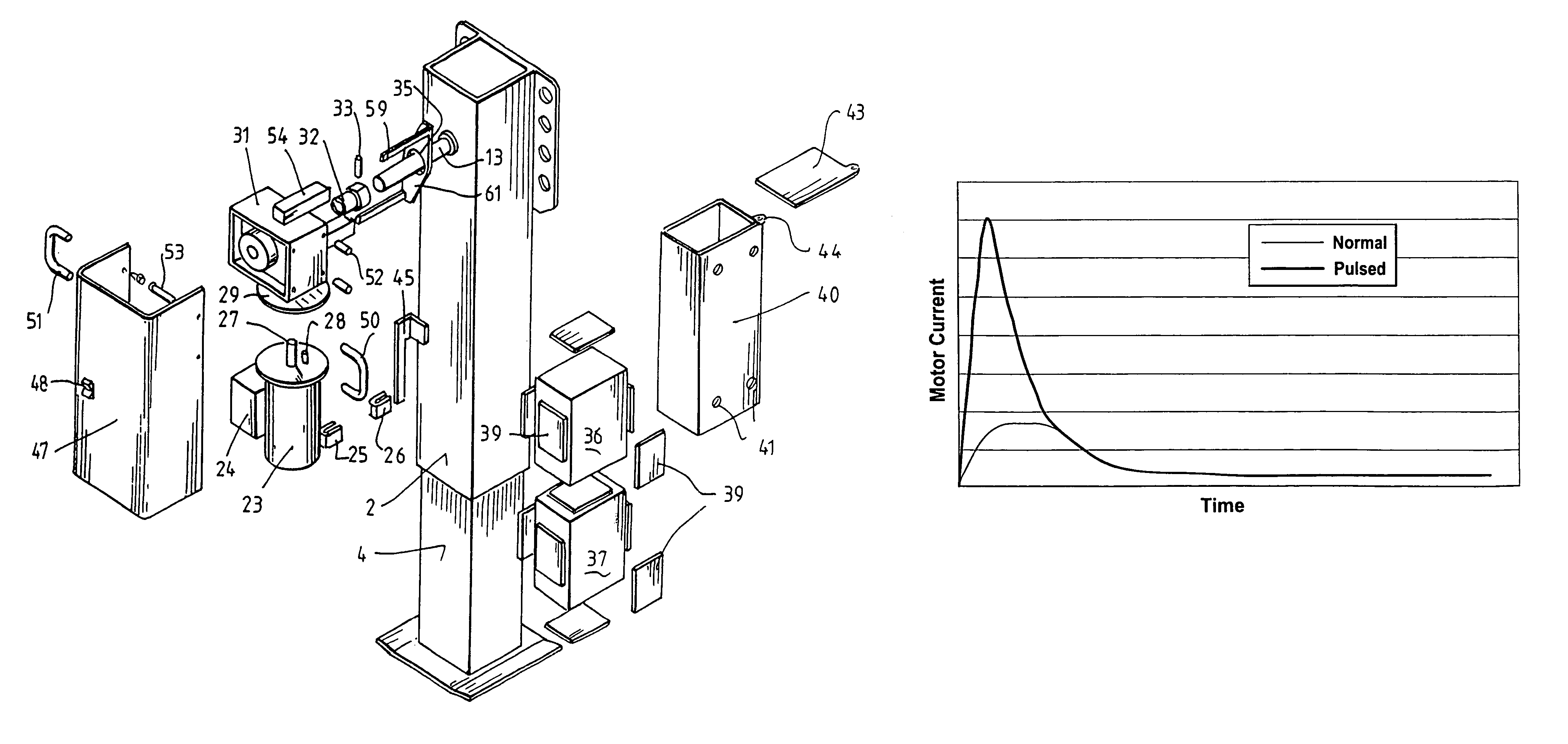
[0160]In a third embodiment, the motor operating current is monitored in small time increments and a maximum allowable current is set as a percentage above the immediate current. In this manner, a significant and rapid increase in the electric motor current will result in shut down of the motor. This feature prolongs motor life and reduces the likelihood of brush burnout.

[0161]In this embodiment shown in FIG. 29, the electric motor is activated by use of electronic relays, usually solid state relays, and known typically as field effect transistors (FET). To avoid a massive rush in current when the motor is turned on, the electric motor voltage is pulsed to effectively cap the current peak. The capping of this peak is illustrated graphically with reference to FIG. 29 which is a plotted motor current against time.


PUM


Abstract

A demountable drive mechanism for coupling to a drive shaft of an operating device, the drive mechanism being directly secured to the drive shaft to cause the drive shaft to rotate, the drive mechanism comprising a geared electric motor having an output for coupling to the drive shaft, the drive mechanism having a torque arm adapted to engage a reaction surface so that the electric motor can impart torque to the drive shaft, and a controller to control operation of the electric motor.

Description

CROSS REFERENCE TO RELATED APPLICATIONS[0001]This application is a Continuation-in-Part of application Ser. No. 09 / 855,752, filed on May 16, 2001 now U.S. Pat No. 6,598,886, which is a Continuation-in-Part of application Ser. No. 09 / 787,711, filed on Jun. 8, 2001, and now abandoned.FIELD OF INVENTION[0002]The present invention relates to a demountable drive mechanism for coupling to a drive shaft of an operating device.BACKGROUND ART[0003]Manual cranking is the most common and simple technique of providing a mechanical advantage for the operation of devices that impart some kind of required displacement. The manual rotary operation of a crank handle is typically converted via gears or racks or the like to, usually, a linear motion of devices such as gates, doors, sides, roofs, decks, platforms and both flexible and rigid covering systems. It is still common today to use human manual effort to operate such devices. Several typical scenarios where manual rotation is required to operat...

Claims


Application Information

Patent Timeline
Patent Type & Authority Patents(United States)
IPC IPC(8): B60S9/02B60P1/56B60P3/34B60S9/08
CPCB60P1/56B60S9/08B60P3/34
Inventor BAIRD, DARRYL W.WATSON, GEOFFREY R.
Owner RAZOR INT
Why Eureka
Try Eureka