Cable connector having a pull tab lock release

a technology of pull-tab and connector, which is applied in the direction of coupling device connection, lighting and heating apparatus, soldering apparatus, etc., can solve the problems of reduced mounting density of connectors and no mechanism, and achieve high-density mounting, reduce the risk of locking arms being damaged or deformed

Inactive Publication Date: 2007-01-16
TYCO ELECTRONICS JAPAN GK
View PDF5 Cites 19 Cited by
  • Summary
  • Abstract
  • Description
  • Claims
  • Application Information

AI Technical Summary

Benefits of technology

[0010]Accordingly, the present invention was devised in light of the problems described above. It is an object of the present invention, among others, to provide a cable connector which enables high-density mounting while reducing the risk of the locking arms being damaged or deformed.

Problems solved by technology

However, this cable connector 101 does not have a mechanism for actively locking with the mating connector, and the pull-tab 112 is not designed to perform the function of releasing the locking mechanism with the mating connector.
Specifically, since the pair of locking arms 212 are required at either end of the housing 210 in the direction of width, the mounting space is correspondingly increased, so that there is a problem in that the mounting density of the connector is reduced.

Method used


Image

  • Cable connector having a pull tab lock release
  • Cable connector having a pull tab lock release
  • Cable connector having a pull tab lock release

Examples


Embodiment Construction

)

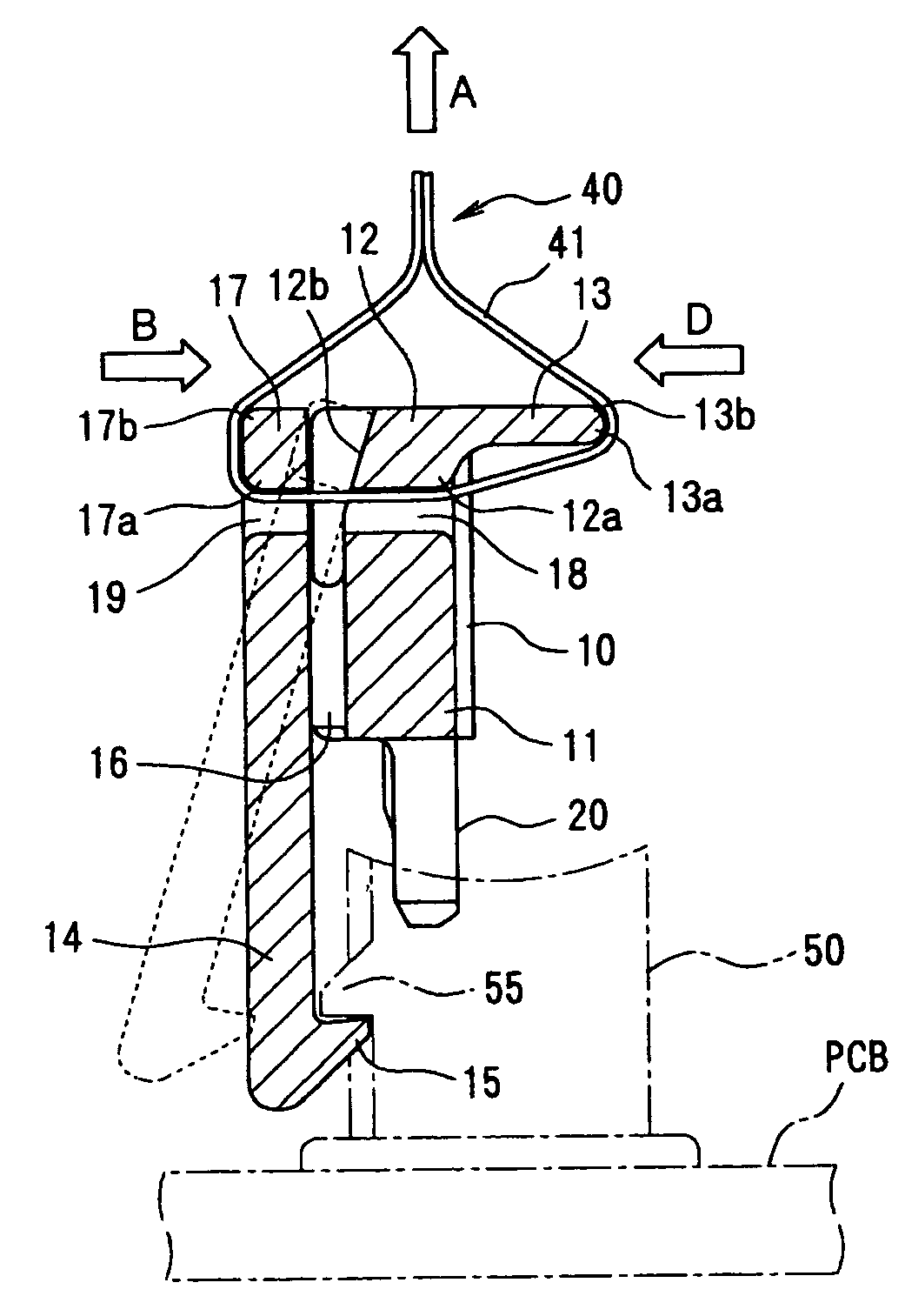
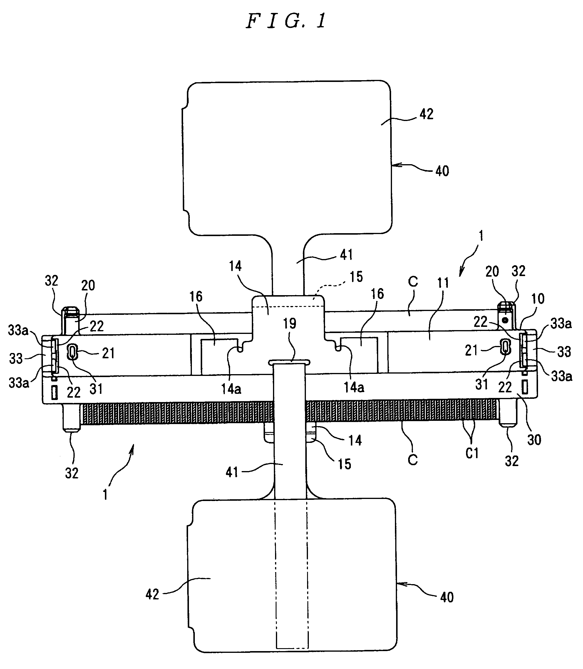
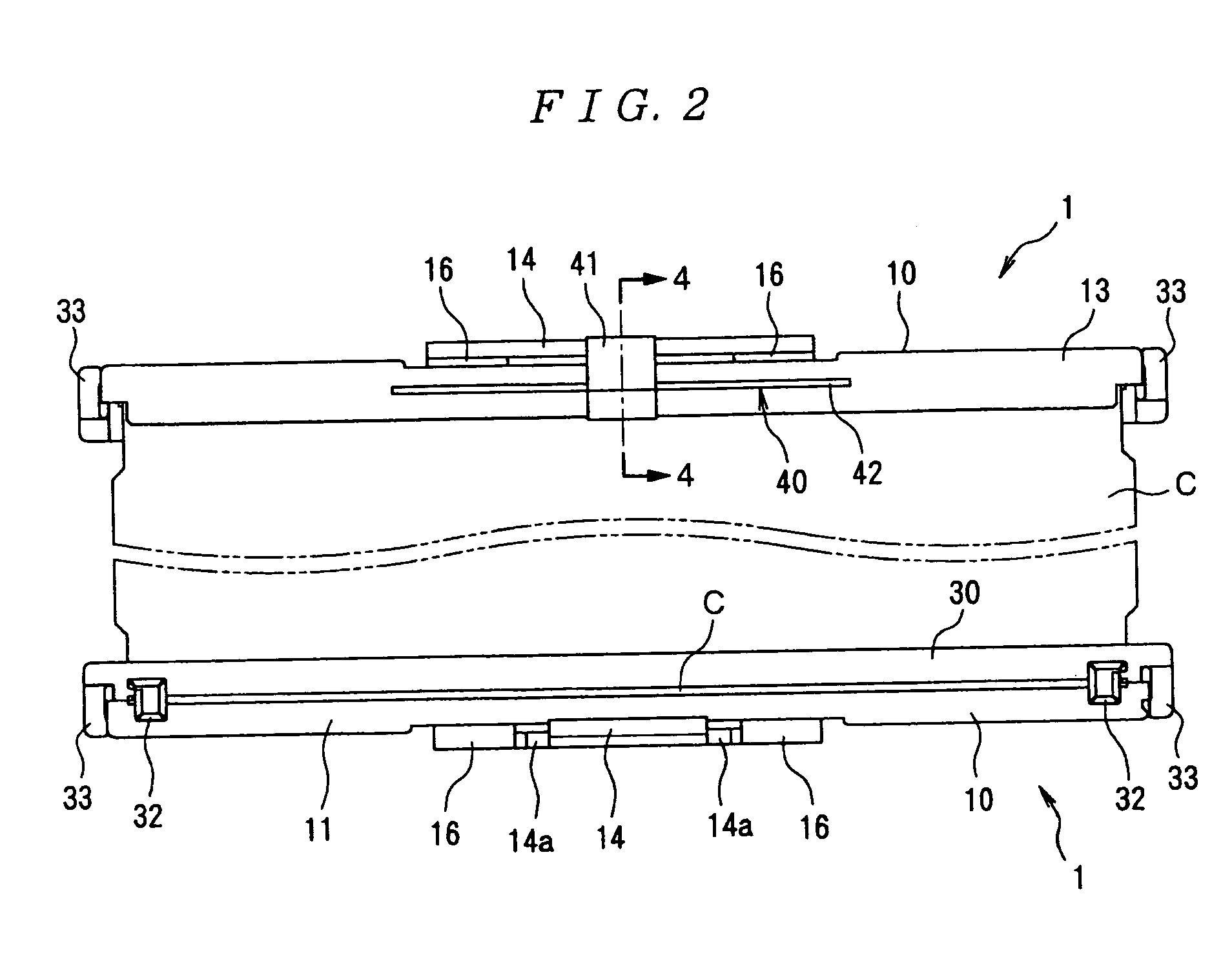
[0020]An embodiment of the present invention will now be described in greater detail with reference to the figures. In FIGS. 1 through 3, a pair of cable connectors 1 is arranged on either end of a cable C such as a flexible flat cable (FFC) such that the tops and bottoms of these cable connectors are inverted relative to each other. As is shown in FIG. 4, each cable connector 1 is designed to mate with a mating connector 50 that is mounted on a circuit board PCB. Since the pair of cable connectors 1 have the same construction and shape, and act in the same manner, the construction and operation of the cable connector 1 that is disposed on one end of the cable C (on the left side in FIG. 3) will be described below.

[0021]Here, the cable connector 1 comprises a first housing 10, a second housing 30, and a pull-tab 40. The first housing 10 and the second housing 30 constitute the “housing” as described herein. The first housing 10 is formed by molding an insulating material, and has a...


PUM

PropertyMeasurementUnit
widthaaaaaaaaaa
elasticityaaaaaaaaaa
forceaaaaaaaaaa

Abstract

A cable connector which enables high-density mounting while reducing the risk of the locking arm being damaged or deformed is disclosed. The cable connector (1) comprises housings (10 and 30) that support a cable (C) and that have a locking arm (14) to be locked with a mating connector (50). A pull-tab (40) is connected to the locking arm (14). The pull-tab (40) is inserted into holes (18 and 19) that are respectively formed in the upper section (12) of the housings (10 and 30) and in the upper section (17) of the locking arm (14). When the pull-tab (40) is pulled in direction approximately opposite from the mating direction (i.e., in the direction of arrow A), the pull-tab (40) causes an approaching motion between the upper section (12) of the housings (10) and (30) and the section (17) of the locking arm (14), thus releasing the locking arm (14) from the mating connector (50).

Description

FIELD OF THE INVENTION[0001]The present invention relates to an electrical connector and more particularly to a cable connector having a pull-tab.BACKGROUND[0002]An example of a known cable connector having a pull-tab is shown in FIG. 6 (see JP63-56563U). The cable connector 101 shown in FIG. 6 comprises a substantially rectangular insulating housing 110 that supports a cable 113. Furthermore, a pull-tab attachment hole 111 that extends in the direction of width of the housing 110 is formed at the end portion of the housing 110, and a pull-tab 112 is attached via the pull-tab attachment hole 111. This cable connector 101 is designed so that following mating with a mating connector (not shown in the figure), it may be released by pulling the pull-tab 112.[0003]However, this cable connector 101 does not have a mechanism for actively locking with the mating connector, and the pull-tab 112 is not designed to perform the function of releasing the locking mechanism with the mating connect...

Claims


Application Information

Patent Timeline
Patent Type & Authority Patents(United States)
IPC IPC(8): H01R13/62
CPCH01R13/6272H01R13/6335H01R12/59B23K9/09B23K9/124B23K9/28B23K9/32B23K35/0261F21K9/238
Inventor MURAYAMA, RYUSUKE
Owner TYCO ELECTRONICS JAPAN GK
Why Eureka
Try Eureka