Electrical connector with shield plate

a shield plate and electric connector technology, applied in the direction of coupling contact members, coupling device connections, printed circuits, etc., can solve the problems of insufficient prevention of facing terminals, difficult to maintain appropriate high-frequency characteristics, and inability to prevent facing terminals sufficiently, so as to improve the high-frequency characteristics of the terminal that functions as the signal terminal, reduce the number of parts, and improve the effect of impedance matching

Active Publication Date: 2019-10-15
HIROSE ELECTRIC GROUP
View PDF12 Cites 12 Cited by
  • Summary
  • Abstract
  • Description
  • Claims
  • Application Information

AI Technical Summary

Benefits of technology

[0007]To address the above-described problems, in a connector including a first terminal group including a plurality of terminals arrayed in a long-side direction at one side, a second terminal group including a plurality of terminals arrayed in the long-side direction at the other side, first ground terminals arranged at both ends of the array of the first terminal group, second ground terminals arranged at both ends of the array of the second terminal group, and an insulating housing that holds the first terminal group, the first ground terminals, the second terminal group, and the second ground terminals; by forming a shield plate arranged between the first terminal group and the second terminal group so that one end of the shield plate is coupled to at least one of the first ground terminals and the other end of the shield plate is coupled to at least one of the second ground terminals; in a case where at least one of a terminal adjacent to the first ground terminal arranged at one side and a terminal adjacent to the second ground terminal facing the first ground terminal functions as a signal terminal; the signal terminal is adjacent to one of the first ground terminals and the second ground terminals, and a crosstalk between the signal terminal and a terminal facing the signal terminal is decreased by the shield plate that functions as a ground by being coupled to at least one of the first ground terminals and the second ground terminals is decreased; and hence there is provided a connector that can improve high-frequency characteristics of the signal terminal, decrease occurrence of an electrically adverse effect such as a crosstalk which may be generated due to a decrease in pitch, and appropriately maintain impedance matching.
[0008]Also, since the shield plate is coupled to at least one of the first ground terminals and the second ground terminals, there is provided a connector that can decrease the number of parts, does not have to be provided with a mount portion extending outside side walls of a housing for connecting the shield plate with a substrate, and that can attain high-density mounting of parts such as a connector and reduction in size of such parts.
[0027]With the connector according to any of the embodiments of the present invention, by forming the shield plate arranged between the first terminal group and the second terminal group to be coupled to the first ground terminal arranged at an end of the array of the first terminal group and the second ground terminal arranged at an end of the array of the second terminal group; in the case where at least one of the terminal adjacent to the first ground terminal and the terminal adjacent to the second ground terminal facing the first ground terminal functions as the signal terminal; a crosstalk which may be generated between the signal terminal and a terminal facing the signal terminal can be blocked by the shield plate that functions as the ground by being coupled to the first ground terminal or the second ground terminal. Accordingly, the high-frequency characteristics of the terminal that functions as the signal terminal can be improved, occurrence of an electrically adverse effect such as a crosstalk which may be generated because of capacitance or induction between mutually facing terminals can be decreased, and impedance matching can be appropriately maintained.
[0028]Also, since the shield plate is coupled to at least one of the first ground terminals and the second ground terminals, the number of parts can be decreased, the mount portion extending outside the side walls of the housing for connecting the shield plate with the substrate does not have to be provided, the high-density mounting and size reduction of parts such as a connector can be attained, occurrence of an electrically adverse effect such as a crosstalk which may be generated because of capacitance or induction between mutually facing terminals can be decreased, and impedance matching can be appropriately maintained.

Problems solved by technology

However, even with the connector including the shield plate like the above-described related-art example, when electric signals are transmitted at further high speed, the adverse effect on impedance matching due to occurrence of a crosstalk between mutually facing terminals cannot be sufficiently prevented, and it is difficult to maintain appropriate high-frequency characteristics.
Hence, the shield plate disturbs the high-density mounting of parts such as a connector on the substrate and disturbs the reduction in size of the connector.
Further, since the shield plate is used in addition to the plurality of terminals having the same shape included in the terminal groups, the number of parts increases, and handling of the parts may be troublesome work when the connector is manufactured.

Method used


Image

  • Electrical connector with shield plate
  • Electrical connector with shield plate
  • Electrical connector with shield plate

Examples


Embodiment Construction

[0041]Embodiments of the present invention will be described below with reference to the drawings. In all the drawings for explaining the embodiments, the same reference signs are basically applied to the same members and the redundant description thereof is omitted. Also, the embodiments are independently described; however, it is not intended to eliminate to configure a connector by combining components of the embodiments.

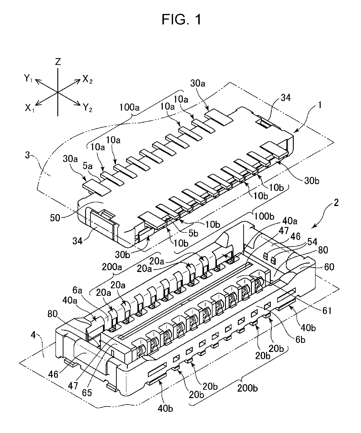
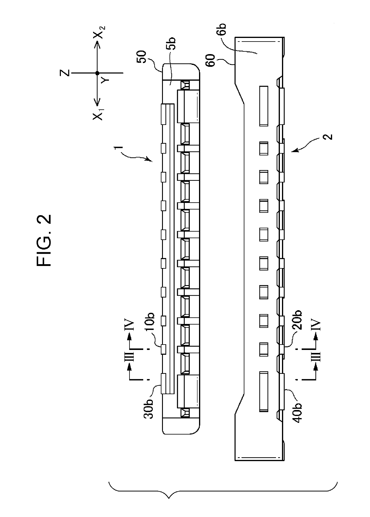
[0042]FIG. 1 illustrates an external appearance of a connector system including a receptacle connector and a plug connector according to an embodiment of the present invention. In FIG. 1, it is assumed that a fitting direction of the connectors is a Z-axis direction, a long-side direction of the connectors is an X-axis direction, and a short-side direction of the connectors is a Y-axis direction. The definition of the directions is also applied to FIGS. 2 to 12. It is assumed that, in the fitting direction (Z-axis direction) of the connectors, a plug connector 1 ...


PUM


Abstract

There is provided a connector that can decrease a crosstalk generated between facing terminals by a shield plate in a case where at least one of a terminal adjacent to a first ground terminal and a terminal adjacent to a second ground terminal facing the first ground terminal functions as a signal terminal, by forming the shield plate so that one end of the shield plate is coupled to the first ground terminal arranged at each of both ends of one terminal group and the other end of the shield plate is coupled to the second ground terminal arranged at each of both ends of the other terminal group.

Description

BACKGROUND OF THE INVENTION1. Field of the Invention[0001]The present invention relates to connectors for connection between substrates, and suitable for high-speed transmission of electric signals. Specifically, the present invention relates to a structure of a connector that, when the connector includes a plurality of terminals arrayed adjacently to one another at narrow pitches, can decrease occurrence of a crosstalk, which may be generated because of capacitance or induction between mutually facing terminals, and can appropriately maintain high-frequency characteristics such as impedance matching. In particular, the present invention relates to a configuration of a connector including a shield plate that can improve the high-frequency characteristics of a signal terminal arranged adjacently to a ground terminal.2. Description of the Related Art[0002]An example of related art to be used for transmitting electric signals etc. may be a connector described in Japanese Patent No. 330...

Claims


Application Information

Patent Timeline
Patent Type & Authority Patents(United States)
IPC IPC(8): H01R12/00H05K1/00H01R13/6585H01R13/6471H01R12/71H01R12/73H01R13/6597H01R13/405
CPCH01R13/6585H01R12/73H01R13/6597H01R13/405H01R12/716H01R13/20H01R13/6582H01R13/652H01R13/6471
Inventor OOI, TETSUYA
Owner HIROSE ELECTRIC GROUP
Why Eureka
Try Eureka