Stent delivery system with hydraulic deployment

a stent and hydraulic technology, applied in the field of stents, can solve the problems of high risk of rupture, high risk of perioperative mortality, and high risk of ruptured aneurysm repair

Inactive Publication Date: 2007-01-16
MEDTRONIC VASCULAR INC
View PDF23 Cites 141 Cited by
  • Summary
  • Abstract
  • Description
  • Claims
  • Application Information

AI Technical Summary

Benefits of technology

[0017]The present invention addresses the problems relating to stent delivery and deployment through the use of a retraction section, which permits the use of at least two different materials to be used for the stent containment portion and the stent retraction section of the stent containment sheath of a stent / stent-graft delivery system. Further, when using a stent retraction section for the efficient retraction of the containment sheath an anti kinking spacer is used to prevent the surrounding containment sheath from kinking and binding. The anti kinking spacer can be made of a weak closely wound helical spring and alternatively the cross section of individual windings of the spring can be tapered to be thick near the central axis and thinner near the perimeter edge. Moreover, a device according to the invention uses fluid pressure within a catheter to retract a stent graft containment sheath to thereby allow the delivery of a stent graft.

Problems solved by technology

The risk of rupture increases with the size of the aneurysm.
The primary risk posed by an abdominal aortic aneurysm is its propensity to rupture.
Emergent surgical repair of a ruptured aneurysm has a high risk (40 to 50 percent) of perioperative mortality.
Medical therapy for abdominal aortic aneurysms is thought to be ineffective in preventing rupture.
Open repair is contraindicated in many patients, usually because of advanced age and associated medical problems.
One problem with presently available stent / stent graft systems lies in the delivery and deployment of the stent / stent graft.
In practice, the use of such a “push-pull” type system is less than ideal.
Both are complex in construction and include numerous pieces, further they present a multi piece large diameter short stent / stent-graft containment sheath that is not well adapted for the needs of insertion of a stent graft placement system which requires the ability to release with smooth reliability without kinking and without binding.

Method used


Image

  • Stent delivery system with hydraulic deployment
  • Stent delivery system with hydraulic deployment
  • Stent delivery system with hydraulic deployment

Examples


Embodiment Construction

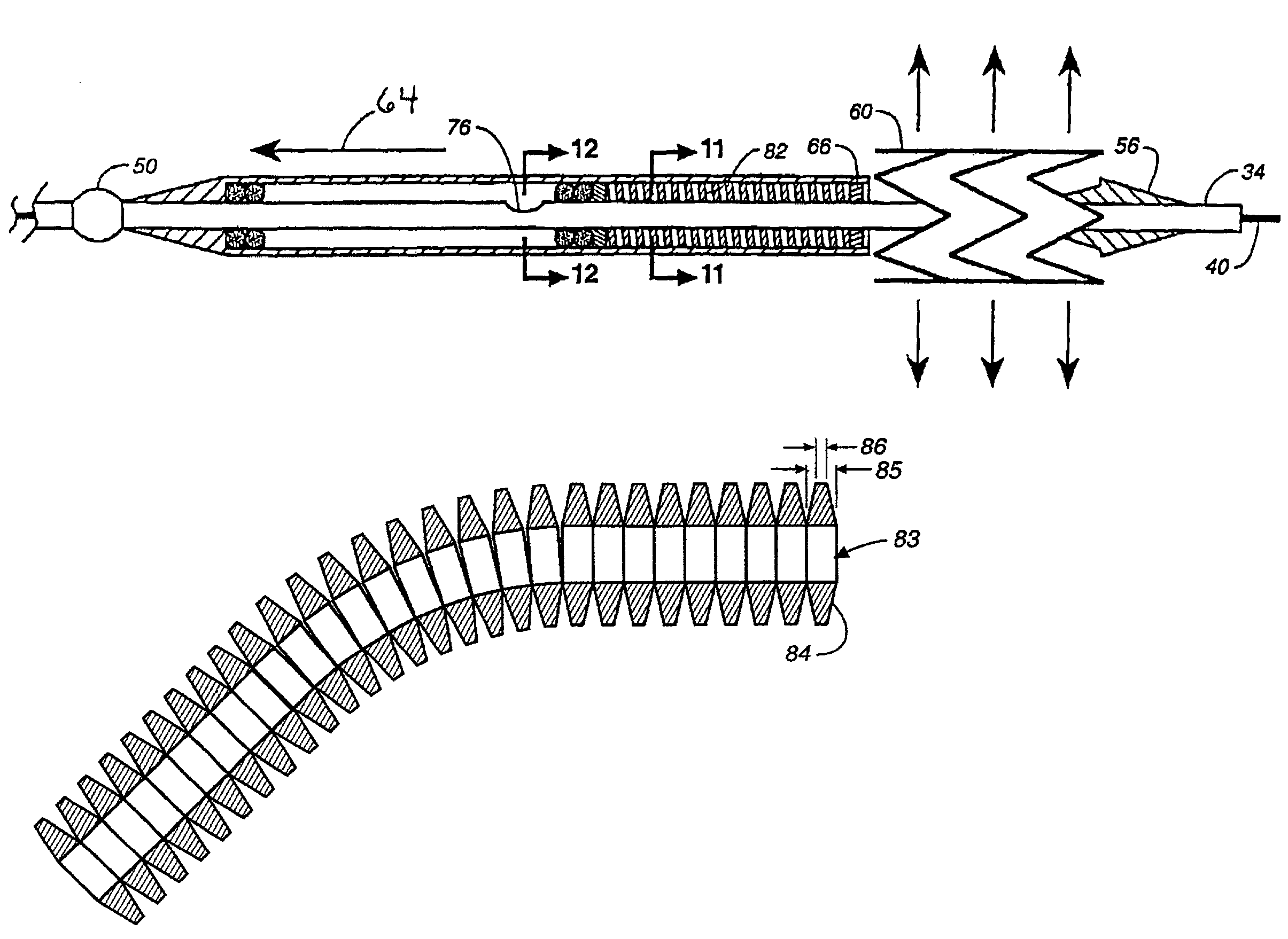
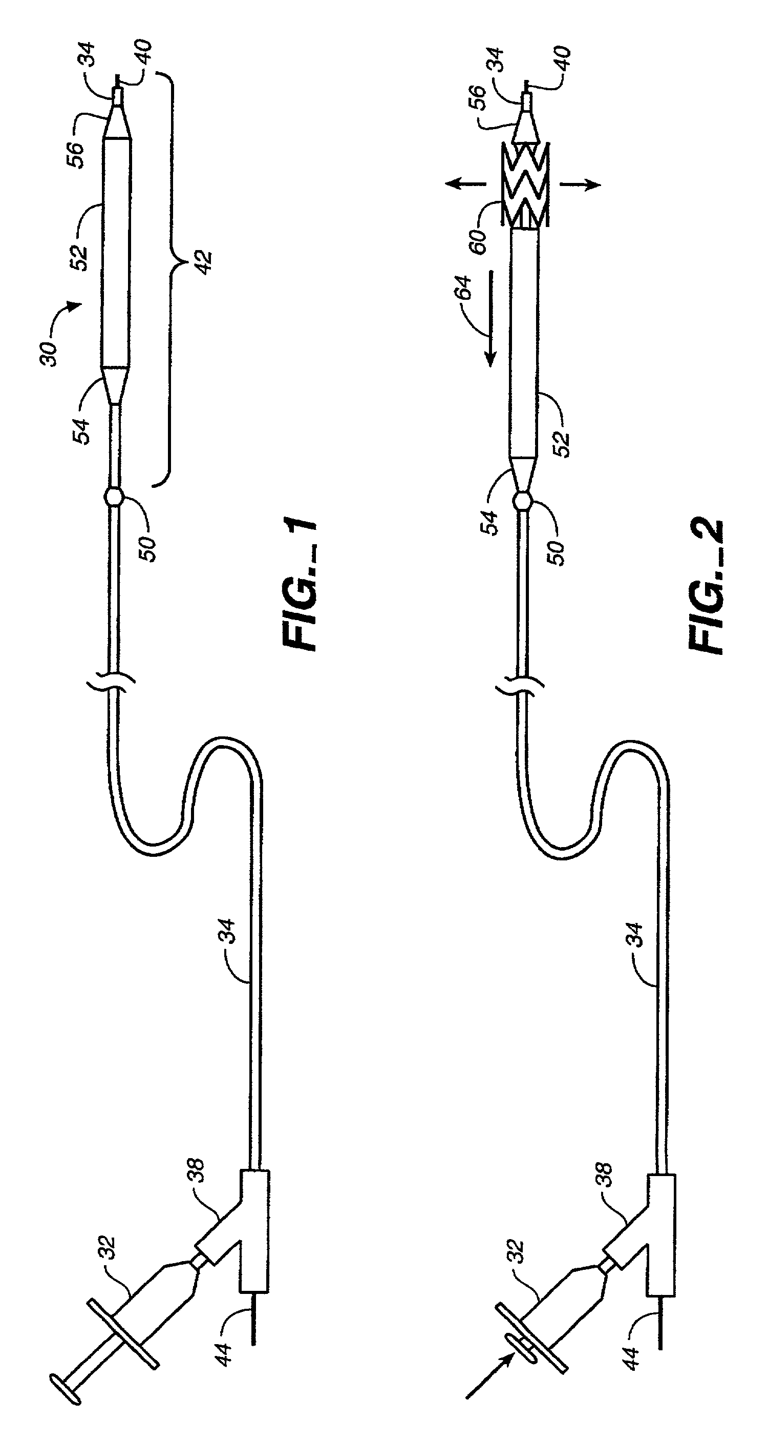
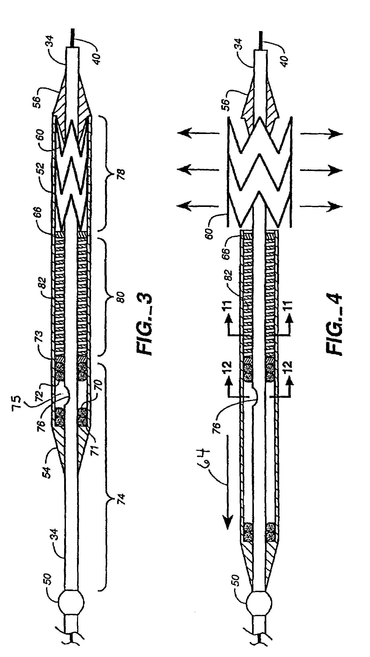
[0033]FIG. 1 is a view of a stent graft system according to the present invention in which the stent graft is not deployed. As seen the system 30 features a source of pressurized fluid, such as a syringe 32, coupled to the catheter body 34 through a Y-type fitting 38. As seen, the catheter body 34 is used typically over a guidewire 40. The guidewire 40, however, may not always be needed or desired to use the system shown. The distal section 42 of catheter body 34 features a backstop 50. The backstop 50 is fixed to the catheter body 34 so as to limit travel of the containment sheath 52. As seen, containment sheath 52 is positioned about and towards the distal end 42 of the catheter body 34. At the proximal end of containment sheath is proximal taper 54. Proximal taper 54 permits the relatively larger diameter containment sheath to be moved within a patient's body, while minimizing the likelihood of sharp edges catching and damaging tissue. Proximal taper 54 further is designed so as ...


PUM


Abstract

A hydraulic stent and stent graft delivery system utilizing at least two different structural materials to effectuate the easy retention and release of the stent and stent graft, while maintaining structural and sealing integrity for a pressurizable fluid chamber. An anti kinking spacer is disclosed which prevents buckling / kinking of the otherwise unsupported sheath containment section when the catheter assembly is bent such as for insertion a movement to the delivery site. A configuration according to the invention provides a flexible small or dual diameter delivery system that uses fluid pressure within the catheter to retract the stent / stent graft containment sheath and allow the delivery and deployment of the stent / stent graft.

Description

PRIORITY CLAIM[0001]This application is a continuation in part application claiming priority from U.S. Provisional Patent Application No. 60 / 240,308, filed on Oct. 13, 2000.FIELD OF THE INVENTION[0002]This invention relates to the field of stents, and more particularly to the field of the delivery and deployment of self-expanding stent grafts.BACKGROUND TO THE INVENTION[0003]The aorta is the main artery of the body, arising from the base of the left ventricle of the heart. It is a large vessel, about one inch in diameter, with thick, elastic walls to withstand the changes in pressure as the heart beats. It supplies oxygenated blood to all arteries except the pulmonary artery (which carries blood to the lungs to be oxygenated). The aorta curves behind the heart and down the chest into the abdomen, where it divides into the two iliac arteries.[0004]A pathologic dilation or balloon like enlargement of the aorta below the renal arteries may occur as a consequence of aging, atheroscleros...

Claims


Application Information

Patent Timeline
Patent Type & Authority Patents(United States)
IPC IPC(8): A61F2/82A61F2/06A61F2/84
CPCA61F2/95A61F2/966A61F2002/9665
Inventor DIAZ, JUAN-CARLOS
Owner MEDTRONIC VASCULAR INC
Why Eureka
Try Eureka