Method and system for testing RFID devices

a radio frequency identification and device technology, applied in the direction of burglar alarm mechanical actuation, instruments, nuclear elements, etc., can solve the problems of less confidence without additional analysis that the test results will be valid to the real life application, and inability to know which of the responding devices is defectiv

Active Publication Date: 2007-01-16
AVERY DENNISON CORP
View PDF14 Cites 46 Cited by
  • Summary
  • Abstract
  • Description
  • Claims
  • Application Information

AI Technical Summary

Problems solved by technology

Unfortunately, the occurrence of defective RFID devices is not trivial, with current estimates of defective RFID devices being as high as about 1–20% of all RFID devices produced.
Such testing may also be performed by the converter prior to dispensing since defects may occur during shipping or handling of the roll after testing by the manufacturer.
One problem with long-range testing is that, because of the proximity of RFID devices to one another on a common carrier web, the interrogation signal emitted from the tester typically elicits responses from a plurality of neighboring RFID devices, many of these responses then being simultaneously detected by the tester.
Because there is currently no way to correlate the responses from the responding RFID devices to the physical locations of the responding RFID devices (since the unique identifiers of the RFID devices typically do not follow a particular sequence and are effectively randomized), even if the reader notes that a defective device is present, there is no way to know which of the responding devices is the detected defective device.
Although short-range testing in general overcomes the problem of multiple devices being simultaneously activated by a single interrogation, the behavior of RFID devices in the near-field reactive region is different from that expected in the near-field and far-field radiating regions, and hence, there is less confidence without additional analysis that the test results will be valid to the real life application.

Method used


Image

  • Method and system for testing RFID devices
  • Method and system for testing RFID devices
  • Method and system for testing RFID devices

Examples


first embodiment

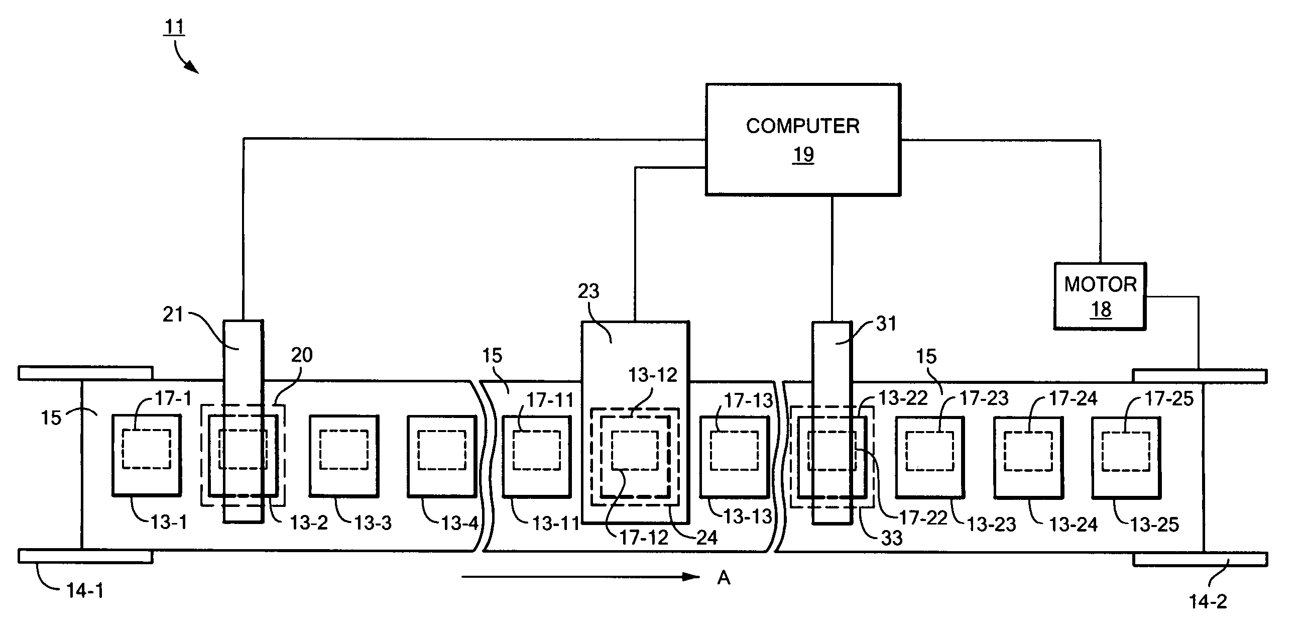
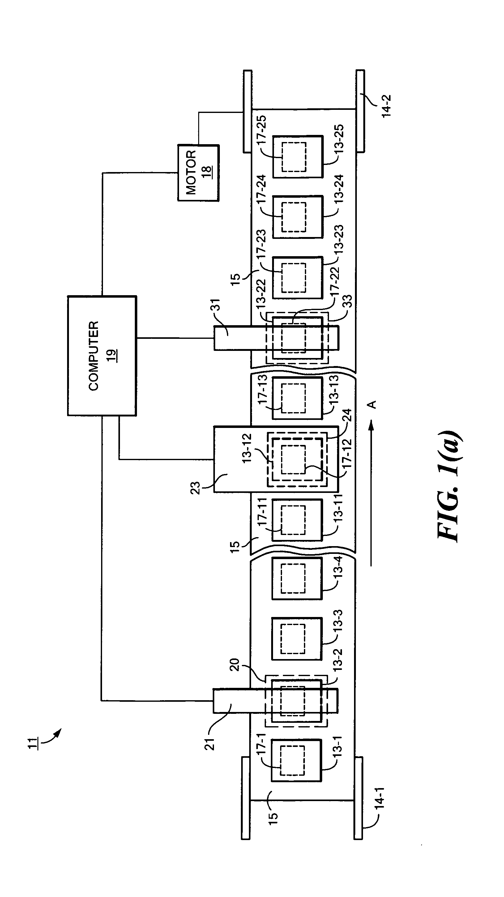
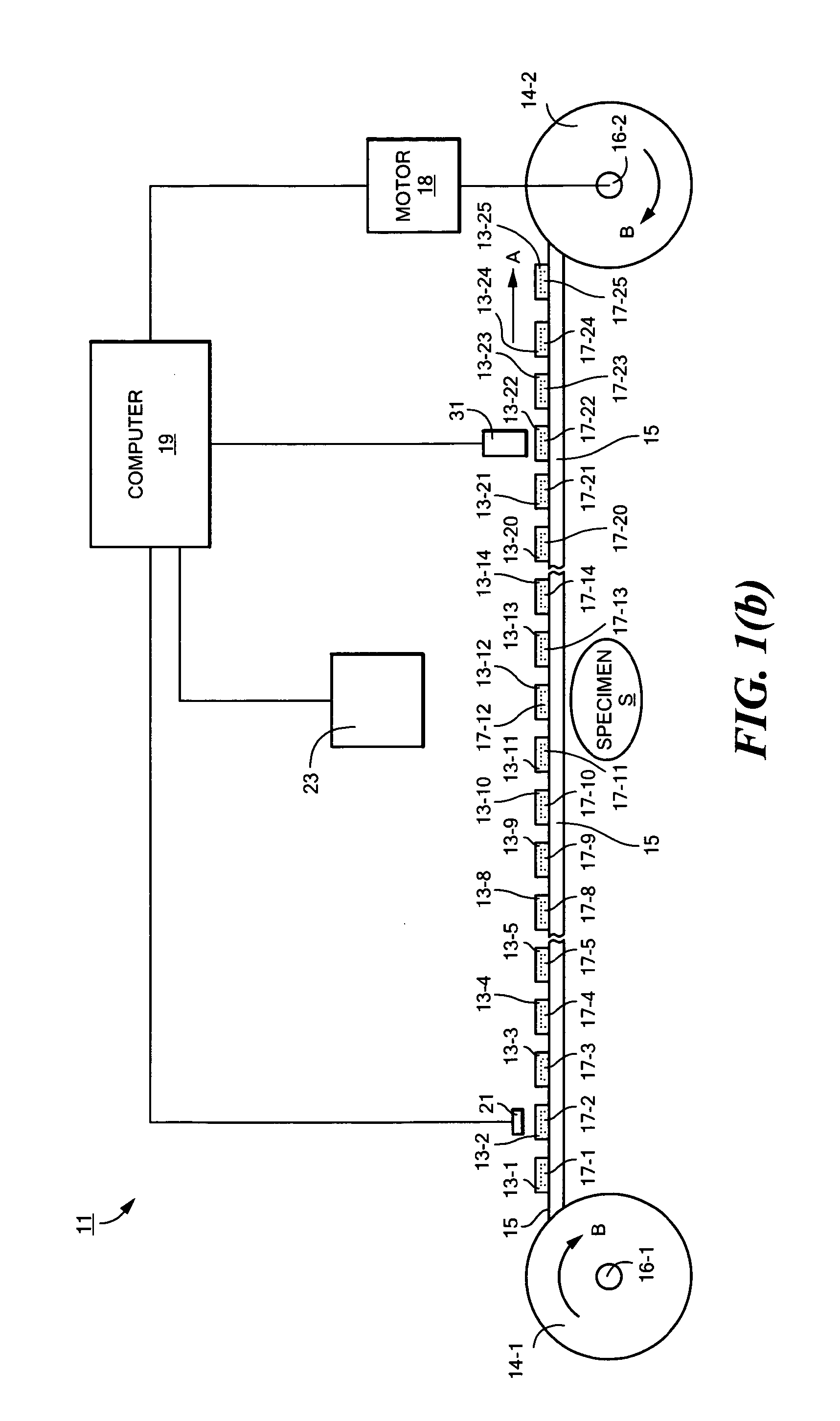
[0026]Referring now to FIGS. 1(a) and 1(b), there are shown fragmentary schematic top and fragmentary schematic side views, respectively, of a system for testing a plurality of RFID devices disposed on a common carrier, the system being constructed according to the teachings of the present invention and represented generally by reference numeral 11. To facilitate an understanding of the construction and operation of system 11, system 11 is shown being used to test a plurality of RFID labels 13-1 through 13-25, RFID labels 13-1 through 13-25 being spaced apart and releasably mounted on a common carrier 15. In the embodiment shown, labels 13 and carrier 15 are presented in roll form and are shown being conducted from an unwind reel 14-1 to a take-up reel 14-2, but it can be appreciated that labels 13 and carrier 15 may alternatively be presented in sheet form. RFID labels 13-1 through 13-25 include IC chips 17-1 through 17-25, respectively (IC chips 17-1 through 17-25 being shown in p...

second embodiment

[0037]Referring now to FIGS. 2(a) and 2(b), there are shown fragmentary schematic top and fragmentary schematic side views, respectively, of a system for testing a plurality of RFID devices disposed on a common carrier, the system being constructed according to the teachings of the present invention and represented generally by reference numeral 111.

[0038]System 111 is similar in many respects to system 11, the principal difference between the two systems being that, in system 111, the respective positions of short-range tester 21 and long-range tester 23 are reversed, as compared to system 11. Consequently, in system 111, short-range tester 21 is positioned in such a way as to test labels located at what is the long-range testing position 24 in system 11, and long-range tester 23 is positioned in such a way as to test labels located at what is the short-range testing position 20 in system 11. As can be appreciated, because of the reversal of positions of short-range tester 21 and l...


PUM

PropertyMeasurementUnit
lengthaaaaaaaaaa
timeaaaaaaaaaa
radio frequencyaaaaaaaaaa

Abstract

A method and system for testing a plurality of RFID devices disposed on a common carrier. In one embodiment, the RFID devices are evenly spaced along the length of the carrier, and the system comprises a short-range tester, a long-range tester and a computer, the short-range tester being coupled to the computer and having a short-range testing position, the long-range tester being coupled to the computer and having a long-range testing position, the long-range testing position being spaced downstream from the short-range testing position by a known number of device positions. In use, an RFID device of interest is first positioned at the short-range testing position, and the short-range tester reads a unique identifier for that RFID device and communicates the identifier to the computer. The carrier is then advanced so that subsequent RFID devices are read by the short-range tester. When the RFID device of interest has advanced to the long-range testing position, the long-range tester conducts a performance test and communicates any detected results to the computer. Because the distance between the two testing positions is known, the computer knows when the RFID device of interest is at the long-range testing position and uses the identifier to distinguish the results for that device from the results of any other devices.

Description

BACKGROUND OF THE INVENTION[0001]The present invention relates generally to methods and systems for testing radio frequency identification (RFID) devices and relates more particularly to a novel method and system for testing RFID devices.[0002]The ability to retrieve information regarding an object of interest in an efficient and wireless manner is critical in many types of situations. For example, many current manufacturing and distribution methods require wireless techniques for retrieval of information regarding objects of inventory, which retrieval techniques can be used, for example, to track the location of an object of inventory from the time of its manufacture to the time of its sale to a customer. One well-known wireless technique for retrieving information relating to an object involves coupling to the object a radio frequency identification (RFID) device that stores pertinent information relating to the object and that wirelessly communicates such information to an electr...

Claims


Application Information

Patent Timeline
Patent Type & Authority Patents(United States)
IPC IPC(8): G08B29/00G01N27/72G01R33/12G08B13/14
CPCG06K7/0008G06K7/10465G06K7/0095G06K7/00
Inventor PULESTON, DAVID JOHNKINGSTON, BENJAMIN JOHNFORSTER, IAN J.
Owner AVERY DENNISON CORP
Why Eureka
Try Eureka