Digital camera and method of controlling the same

Inactive Publication Date: 2007-01-16
FUJIFILM CORP
View PDF6 Cites 44 Cited by
  • Summary
  • Abstract
  • Description
  • Claims
  • Application Information

AI Technical Summary

Benefits of technology

[0011]According to the present invention, when the strobe irradiation distance d obtained on the basis of the f-stop value F of the zoom lens is shorter than the distance to the subject, that is, when the subject is positioned beyond the strobe irradiation distance d, the amplification factor for amplifying the image signal representing the subject image obtained by the imaging is made higher than a normal amplification factor. The subject image is brightened by increasing the amplification factor. On the other hand, when the subject is positioned within the strobe irradiation distance d, the amplification factor is not increased. If the subject is positioned within the strobe irradiation distance d, a subject image having predetermine

Problems solved by technology

However, a small-sized camera having a zoom lens employs such a lens structure that the f-stop value of the zoom lens is increased if the focal distance thereof is increased because it is generally difficult to employ such a lens structure that the f-stop

Method used


Image

  • Digital camera and method of controlling the same
  • Digital camera and method of controlling the same
  • Digital camera and method of controlling the same

Examples


Embodiment Construction

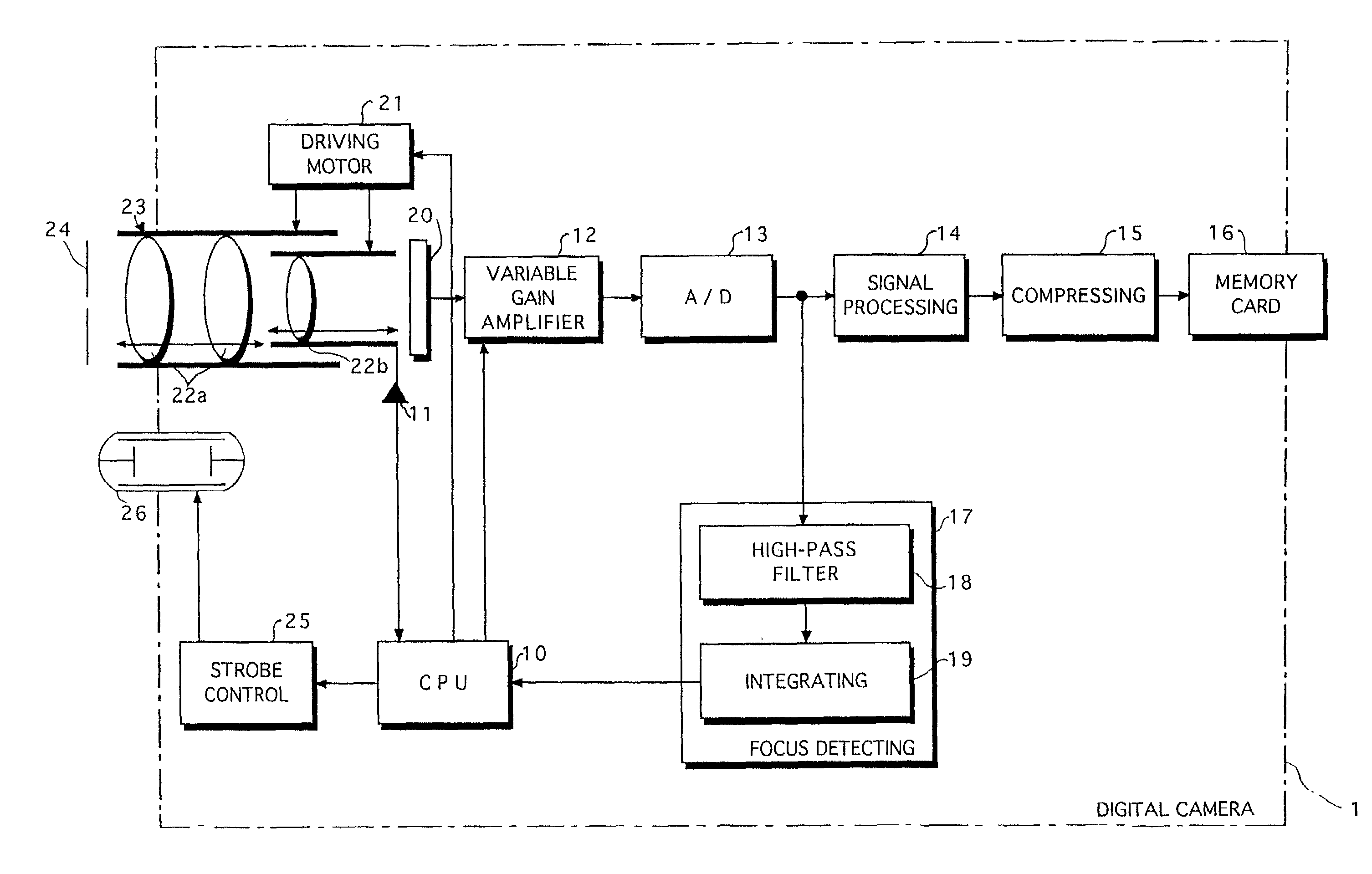
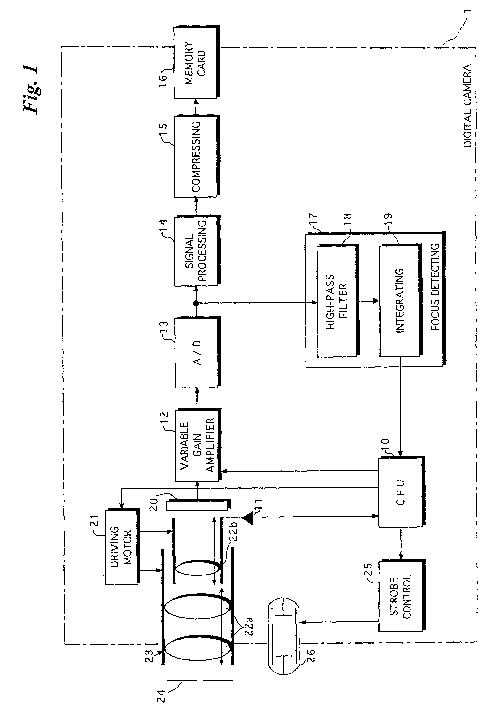
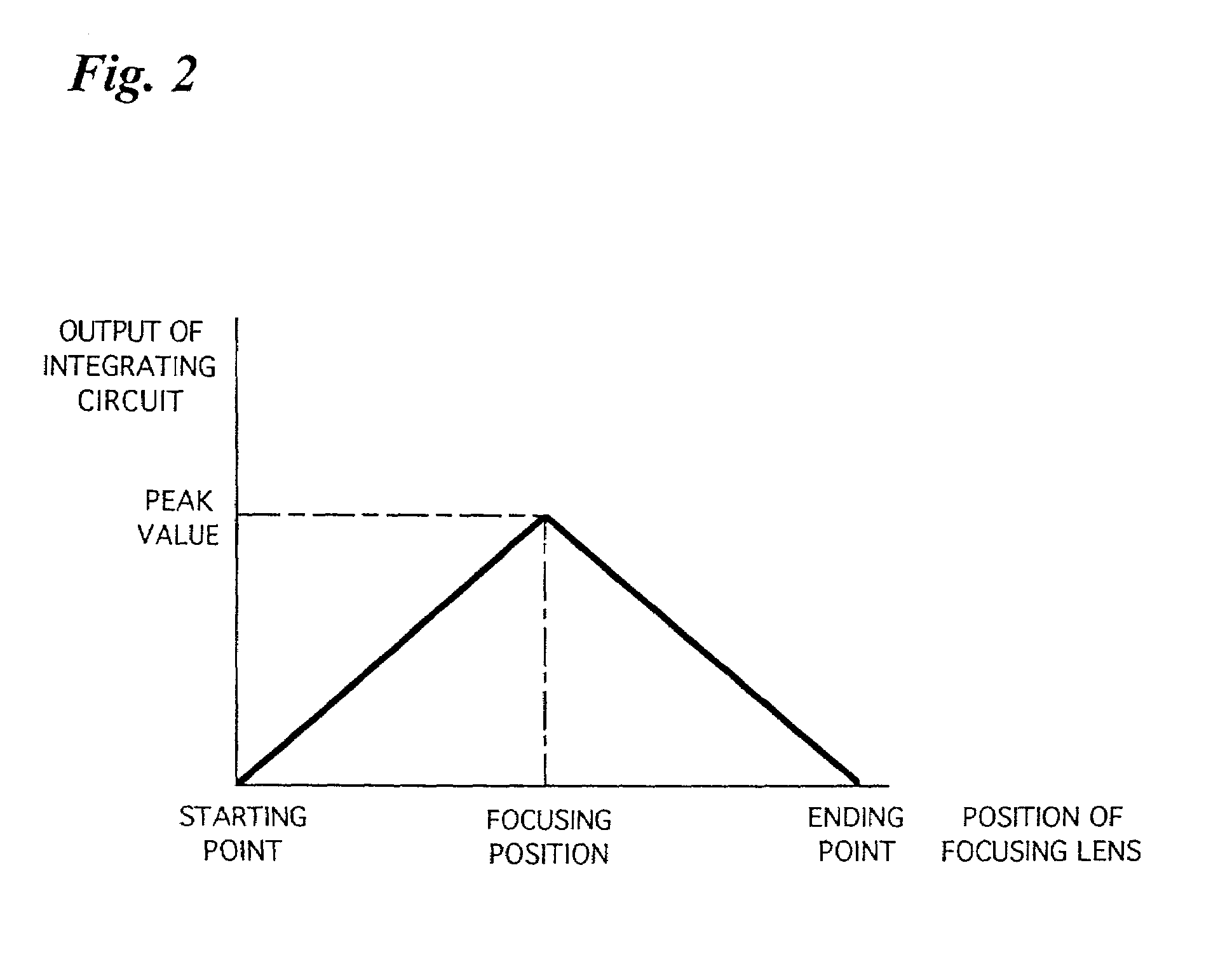
[0024]FIG. 1 is a block diagram showing the electrical configuration of a digital camera 1. FIG. 2 is a graph showing an example of the change of an output signal from an integrating circuit 19 contained in the digital camera 1.

[0025]The digital camera 1 comprises a CPU 10. The digital camera 1 is supervised and controlled by the CPU 10.

[0026]The digital camera 1 comprises an optical unit 23. The optical unit 23 has a group of lenses comprising a plurality of lenses. The group of lenses includes a zoom lens(es) 22a for zooming and a focusing lens 22b for focusing. The zoom lens 22a and the focusing lens 22b are moved by a driving motor(s) 21 controlled by a control instruction issued from the CPU 10.

[0027]Furthermore, the digital camera 1 includes an aperture (iris or diaphragm) 24 for adjusting the amount of light. The aperture 24 is controlled by the driving motor(s) 21.

[0028]The digital camera 1 further includes a starting point sensor 11. The focusing lens 22b is moved between a...


PUM


Abstract

The present invention is directed to obtaining an image having predetermined brightness, while making the degradation of the image as little as possible. A distance (an irradiation distance d) at which a predetermined amount of reflected light can be obtained is obtained from the guide number Gn of a strobe and the f-stop value F (the focal distance f of a zoom lens). When the strobe is used, it is judged whether or not a subject is positioned within the irradiation distance d. When the irradiation distance d of the strobe is shorter than the distance to the subject, that is, the subject is beyond the irradiation distance d of the strobe, an imaging signal is amplified than usual.

Description

BACKGROUND OF THE INVENTION[0001]1. Field of the Invention[0002]The present invention relates to a digital camera and a method of controlling the same.[0003]2. Description of the Background Art[0004]In digital cameras having a zoom lens, the focal distance of the zoom lens can be continuously changed by moving the zoom lens. When the focal distance is increased, an image formed on an imaging surface is made large, thereby obtaining a telephotographic effect. When the focal distance is decreased, the image formed on the imaging surface is made small, thereby making wide-angle imaging possible.[0005]A single-lens reflex camera, for example, of cameras having a zoom lens can employ such a lens structure that the f-stop value of the zoom lens is not changed even if the focal distance thereof is changed. However, a small-sized camera having a zoom lens employs such a lens structure that the f-stop value of the zoom lens is increased if the focal distance thereof is increased because it i...

Claims


Application Information

Patent Timeline
IPC IPC(8): H04N5/232H04N5/222H04N5/243H04N5/235H04N101/00
CPCH04N5/23212H04N5/2354H04N5/2352H04N23/673H04N23/72H04N23/74
Inventor KONISHI, MASAHIRO
Owner FUJIFILM CORP
Why Eureka
Try Eureka