Light-guide lights suitable for use in illuminated displays

a technology of light-guide lights and illuminated displays, which is applied in waveguides, lighting and heating apparatuses, instruments, etc., can solve the problems of affecting the overall visual appearance and effectiveness of illumination, and achieve the effects of reducing the production cost, and improving the overall visual appearan

Inactive Publication Date: 2007-01-16
3M INNOVATIVE PROPERTIES CO
View PDF16 Cites 30 Cited by
  • Summary
  • Abstract
  • Description
  • Claims
  • Application Information

AI Technical Summary

Benefits of technology

[0008]The present invention is directed to the problem of providing a light-guide light which is suitable for display purposes and capable of meeting the demands for uniform illumination and efficiency, and which can be assembled comparatively easily in a variety of sizes.
[0014]Light-guide lights in accordance with the invention can be produced comparatively easily in different sizes in a manner that is appropriate to bespoke production, and can offer effective, uniform, and efficient illumination for display purposes and for other lighting applications.

Problems solved by technology

One problem with many display panels is that the panel is more brightly illuminated in the area closest to the light source, which detracts from the overall visual appearance and effectiveness of the illumination.

Method used


Image

  • Light-guide lights suitable for use in illuminated displays
  • Light-guide lights suitable for use in illuminated displays
  • Light-guide lights suitable for use in illuminated displays

Examples


example i

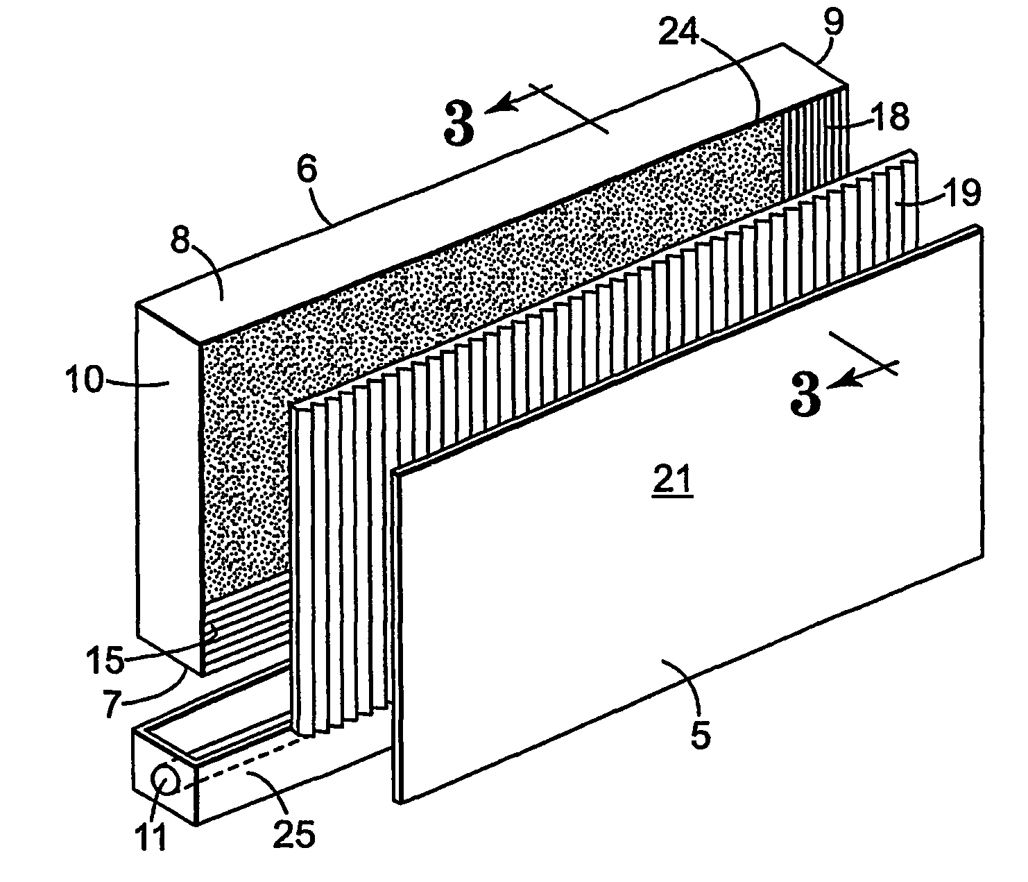
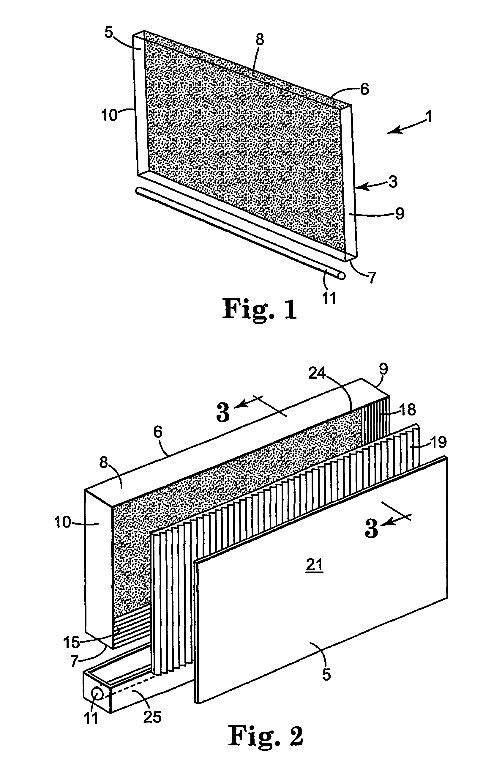
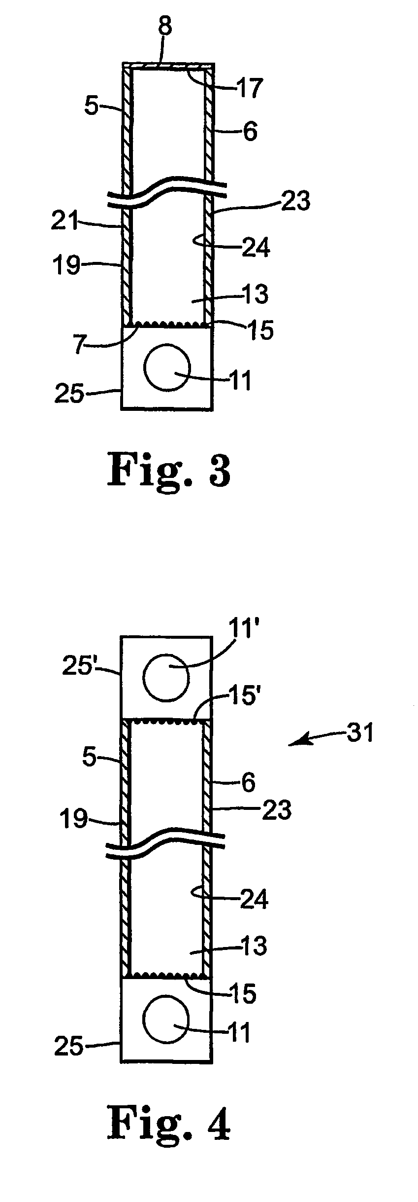
[0039]The housing 3 of the light guide 1, excluding the front major face 5, may be a one-piece vacuum-formed construction of any suitable material, for example PVC (polyvinylchloride). Alternatively, the housing may be formed from several pieces of, for example, an acrylic material, each providing one side of the housing, which are secured together in any suitable manner. The housing is approximately 60×60×4.5 cm.

[0040]The internal surface of the rear major face 6 of the housing is covered with a sheet 23 of 3M™“Radiant Light Film Embossed VM2000”. The internal surface of one narrow side 7 of the housing 3 is covered with a sheet 15 of the above-mentioned “Scotch™ Optical Lighting Film”, arranged with the prisms facing into the housing and extending parallel to the long edges of this side of the housing. The internal surface of the opposite narrow side 8 of the housing 3 is covered with a sheet of the above-mentioned “VM2000 Radiant Mirror Film.” The internal surfaces of the remaini...

example ii

[0043]A light guide module similar to that described in Example I was constructed except that the housing 3 of the light guide was larger, having dimensions of approximately 120×180×6 cms. In addition, the optical sheet material 15 on the narrow side 7 of the housing 3 was omitted and the housing 25 for the lighting tube 11 was by a housing 40 illustrated diagrammatically in FIG. 6 which also illustrates the disposition of the housing relative to the narrow side 7 of the light guide housing 3. The lighting tube housing 40, which is separate from the light guide housing 3, extends along the length of the lighting tube (indicated in FIG. 6 by the reference 41) and thus along length of the side 7 of the light guide housing. The housing 40 includes a back portion 42 that is located to the rear of the lighting tube 41, and diverging flat sides 43 that extend from each front edge 44 of the back portion 42 towards the light guide housing 3. The diverging sides 43 define an exit opening thr...


PUM


Abstract

A light-guide light (1) suitable for use in illuminated displays and signs comprises a housing (3) defining an optical cavity having first and second generally parallel major faces (5, 6), and a light source (11) positioned to direct light into the optical cavity from one side. The first major face (5) comprises a material (for example, a prismatic film) having coefficients of reflection and transmission that vary with the angle at which light is incident on the material. The second major face (6) comprises a narrow-scattering reflective material having a reflectance of at least 85%, for example a highly-efficient reflective material provided with a suitable textured pattern.

Description

FIELD OF THE INVENTION [0001]The present invention relates to a light-guide light capable of providing an illuminated panel and suitable for use, for example, in illuminated displays and signs and in other lighting applications.BACKGROUND OF THE INVENTION [0002]It is already known to use light guides to illuminate panels for general lighting purposes and also for display applications (e.g. for illuminating signs and advertisements, and also for illuminating liquid crystal displays). In one form, often referred to as a light box, the light guide comprises a hollow box-shaped structure defining an optical cavity, and in another form it comprises a solid light-guiding plate. In both forms, a major surface of the guide can be illuminated by light directed into the guide in a direction generally parallel to that major surface, for example from at least one elongated light source or a similar arrangement located adjacent an edge of the light guide (so-called “edge-lit light guides”).[0003...

Claims


Application Information

Patent Timeline
Patent Type & Authority Patents(United States)
IPC IPC(8): G02B6/10H01J5/16F21V8/00F21Y103/00G09F13/16G09F13/18
CPCG09F13/16G09F13/18Y10S385/901
Inventor WRIGHT, JOHN C.LEA, MICHAEL C.
Owner 3M INNOVATIVE PROPERTIES CO
Why Eureka
Try Eureka