Pivotal device for scissors

a pivot device and scissors technology, applied in the field of pivot devices for scissors, can solve problems such as interference with the operation of scissors, and achieve the effect of reducing the risk of loosening of screws and/or nuts, and less likely to mov

Inactive Publication Date: 2007-01-23
YEH WEN YA
View PDF10 Cites 2 Cited by
  • Summary
  • Abstract
  • Description
  • Claims
  • Application Information

AI Technical Summary

Benefits of technology

[0013]Thus, the contact area between the screw and the pivotable scissor elements is small as compared to the conventional designs. Thus, the screw is less likely to move when the scissor elements pivot. The risk of loosening of the screw and / or the nut is reduced. A reliable pivotal arrangement is provided accordingly.

Problems solved by technology

Further, the exposed nut 6 may interfere with operation of the pair of scissors.

Method used


Image

  • Pivotal device for scissors
  • Pivotal device for scissors
  • Pivotal device for scissors

Examples


Embodiment Construction

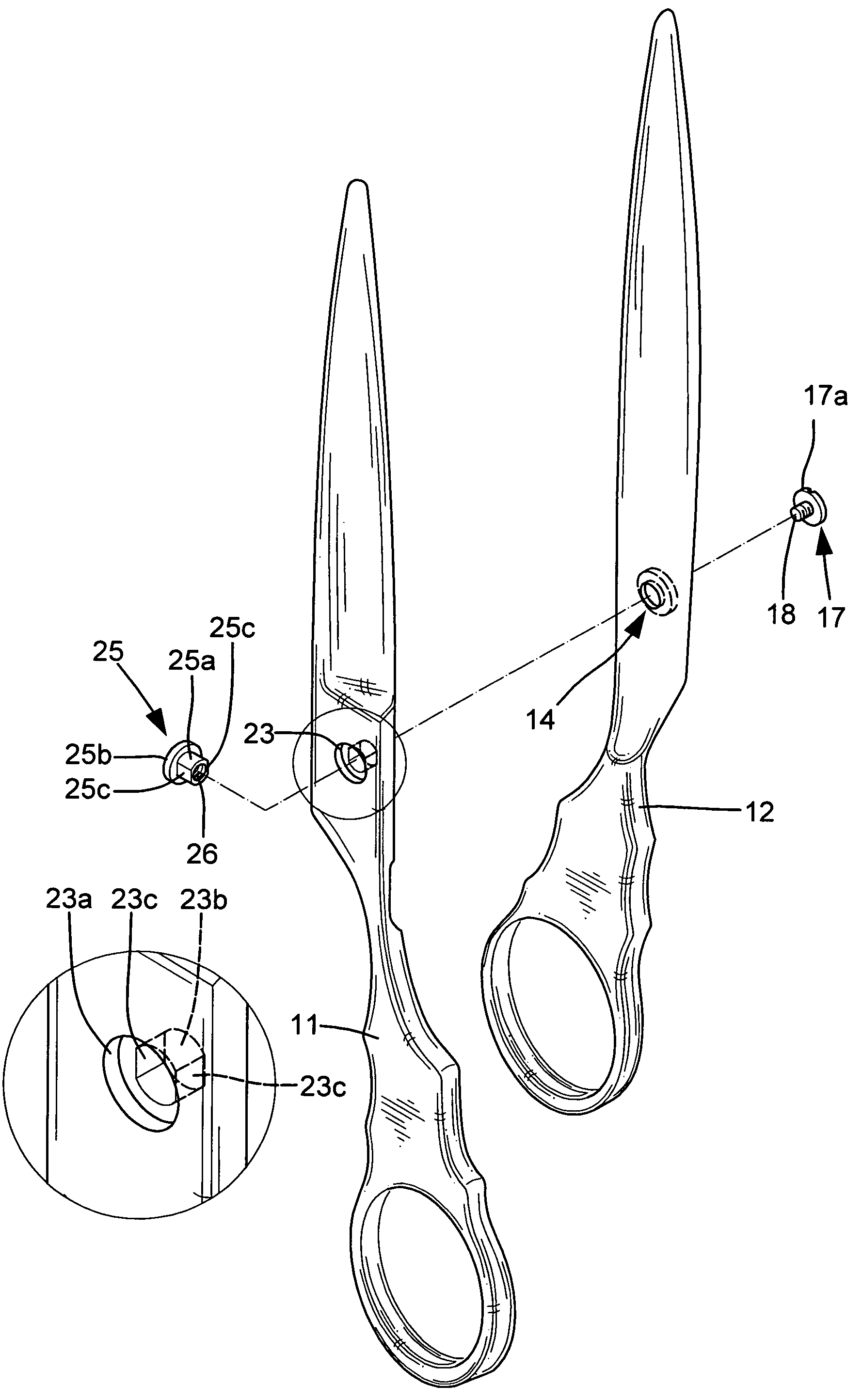
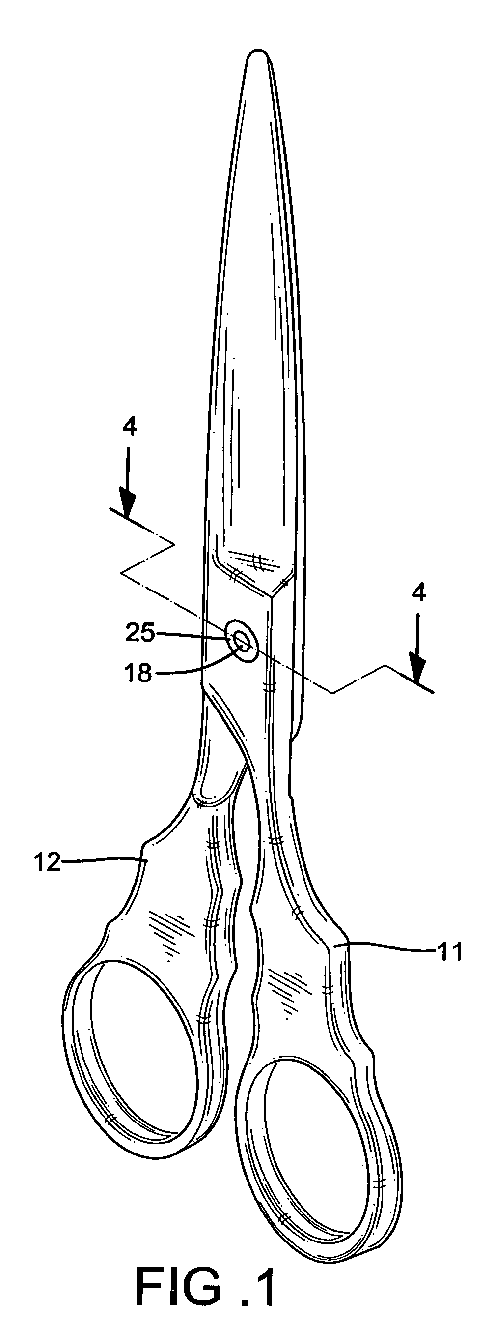
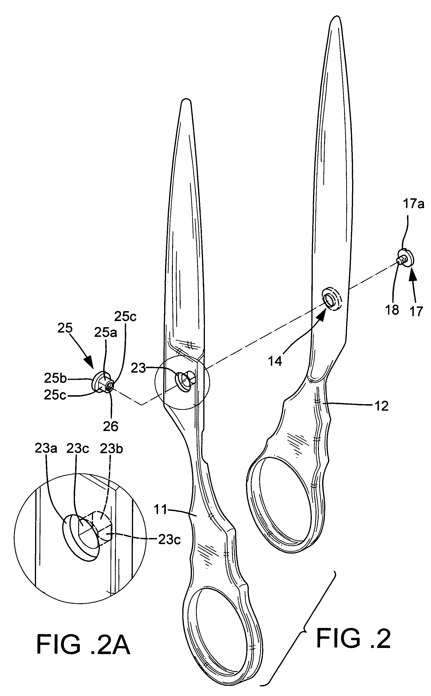
[0031]Referring to FIGS. 1 through 5, a pair of scissors in accordance with the present invention comprises a first scissor element 11, a second scissor element 12, and a pivotal device for pivotally engaging the first scissor element 11 with the second scissor element 12.

[0032]As illustrated in FIGS. 2, 2A, and 4, the first scissor element 11 includes a countersink 23 extending from a first side of the first scissor element 11 through a second side of the first scissor element 11. The countersink 23 of the first scissor element 11 has a larger section 23a facing away from the second scissor element 12 and a smaller section 23b facing the second scissor element 12. It is noted that the smaller section 23b is substantially circular and includes two flat portions 23c parallel to each other. In other words, the smaller section 23b is non-circular.

[0033]As illustrated in FIGS. 2 and 4, the second scissor element 12 includes a countersink 14 extending from a first side of the second scis...


PUM


Abstract

A pair of scissors includes two scissor elements and a pivotal device. Each scissor element includes a countersink extending from a first side thereof through a second side thereof. The pivotal device includes a screw and a nut. The screw includes a threaded shank and an enlarged head. The nut includes a non-circular shank and an enlarged head, with a screw hole extending through the non-circular shank and the enlarged head of the nut. The nut is received in the countersink of one of the scissor elements, with the non-circular shank of the nut extending into a non-circular countersink of the other scissor element. The threaded shank of the screw is threadedly engaged with the screw hole of the nut. Thus, the contact area between the screw and the pivotable scissor elements is small.

Description

CROSS REFERENCE TO RELATED APPLICATION[0001]This is a continuation-in-part application of U.S. patent application Ser. No. 10 / 784,621 filed Feb. 23, 2004, now U.S. Pat. No. 6,904,685.BACKGROUND OF THE INVENTION[0002]1. Field of the Invention[0003]The present invention relates to a pivotal device for a pair of scissors.[0004]2. Description of the Related Art[0005]FIGS. 9 and 10 of the drawings illustrate a pair of conventional scissors including a scissor element 1 and a second scissor element 2. The first scissor element 1 and the second scissor element 2 are pivotally connected by a pivotal device consisting of a bolt or screw 4 and a nut 6. As illustrated in FIG. 10, the first scissor element 1 includes a through-hole 7 extending from a side of the first scissor element 1 through the other side of the first scissor element 1. Further, the second scissor element 2 includes a countersink 8 extending from a side of the second scissor element 2 through the other side of the second sci...

Claims


Application Information

Patent Timeline
Patent Type & Authority Patents(United States)
IPC IPC(8): B26B13/28
CPCB26B13/28
Inventor YEH, WEN-YA
Owner YEH WEN YA
Why Eureka
Try Eureka