Toric reinforced air bag for safety tire and method of producing the same as well as method of producing shaped body for reinforcing layer

a technology of reinforced air bags and safety tires, which is applied in the direction of inflatable tyres, vehicle components, and separate inflatable inserts, can solve the problems of difficult to accurately arrange the reinforcing layer, and achieve the effect of forming operation efficiency

Inactive Publication Date: 2007-01-23
BRIDGESTONE CORP
View PDF29 Cites 6 Cited by
  • Summary
  • Abstract
  • Description
  • Claims
  • Application Information

AI Technical Summary

Benefits of technology

[0013]Even if cracks are created in the reinforcing layer by sticking a foreign matter entered from the punctured hole into the interior of the tire or the like, since the reinforcing layer and the toric air bag are separated from each other at a time of creating the crack in the reinforcing layer, the propagation of the crack from the reinforcing layer to the toric air bag can be effectively suppressed.
[0049]According to this method, the narrow-width strip of the composite body is applied onto the outer surface of the shape-stable hard support to form a shaped body for a reinforcing layer as an uncured reinforcing layer, whereby the strip can be always and properly applied onto the support without the occurrence of wrinkles or the like as is expected to simply and easily form the shaped body for the reinforcing layer having the required shape and size.

Problems solved by technology

Also, in order to produce the toric reinforced air bag by integrally uniting the reinforcing layer 103 with the air bag 102 through vulcanization, it is necessary that a starting material for the reinforcing layer is applied onto an outer peripheral face of an uncured air bag having an unstable shape over a given region while suppressing an expansion shape of the uncured air bag as is expected, if necessary, and both the materials are joined through vulcanization, so that there is finally caused a problem that it is difficult to accurately arrange the reinforcing layer 103 on a given position of the air bag 102.

Method used


Image

  • Toric reinforced air bag for safety tire and method of producing the same as well as method of producing shaped body for reinforcing layer
  • Toric reinforced air bag for safety tire and method of producing the same as well as method of producing shaped body for reinforcing layer
  • Toric reinforced air bag for safety tire and method of producing the same as well as method of producing shaped body for reinforcing layer

Examples


example 1

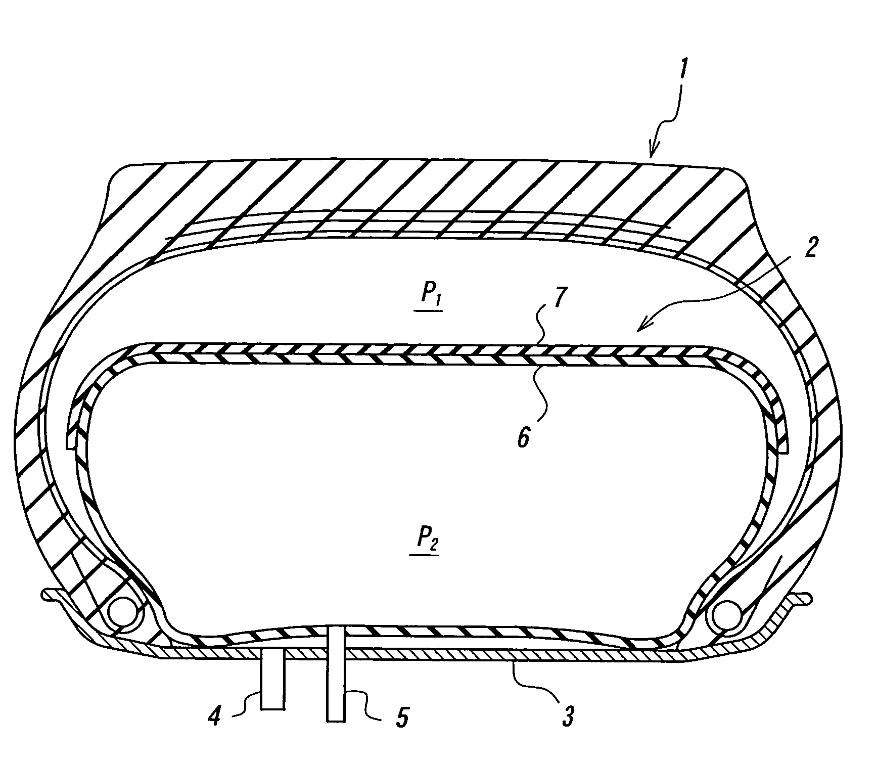
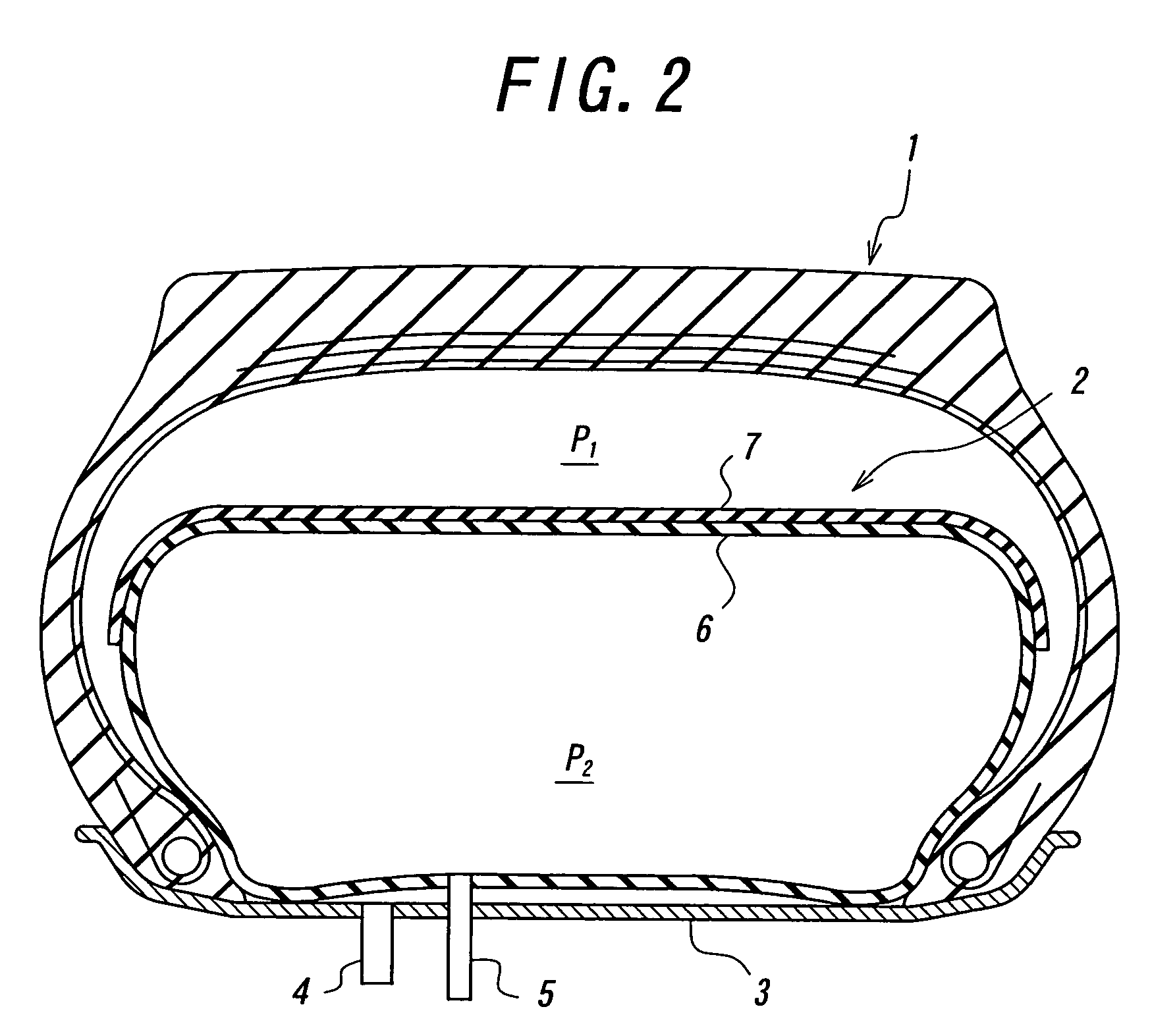
[0116]There are provided invention safety tires having a structure shown in FIG. 2 and a tire size of 315 / 60R22.5 (defined in ETRTO 2000), in which a carcass is comprised of one carcass ply having a radial structure of steel cords, and a reinforcing layer is made of a composite material of a non-woven fabric and a rubber composition, and a toric air bag is made of a soft rubber for a tire tube, and a ratio of the reinforcing layer to a periphery length of the toric air bag and an adhesion strength therebetween are changed, respectively. After each of these tires is assembled onto a standard rim, a running endurance test under conditions that an air pressure filled in the tire is 900 kPa as a gauge pressure and an air pressure filled in the toric reinforced air bag is 950 kPa as a gauge pressure, and a running endurance test under low pressure condition that an internal pressure of the toric reinforced air bag is 450 kPa through its expansion deformation at a puncture state of render...

example 2

[0123]With respect to invention tires in which the structure of the reinforcing layer is variously changed and the ratio of the reinforcing layer to the periphery length of the toric air bag is 60% and the adhesion strength therebetween is 1.5 kN / m, the running endurance test and the running endurance test under low pressure are conducted under the same conditions as in Example 1 to obtain results as shown in Table 2.

[0124]Even in this case, the larger the index value, the better the result.

[0125]

TABLE 2Invention Tires15161718192021Structure ofwidth of strip (mm) 40 40 5 30 40 50 80reinforcingbuilding directionperipheralperipheralperipheralperipheralperipheralperipheralperipherallayeroverlap◯◯◯◯◯◯◯side face contactXXXXXXXinclination angle width 10 10 10 5 10 10 10respect to peripheraldirection (°)strip lengthfibrous memberstraightwavywavynon-wovennon-wovennon-wovennon-wovenorganicorganicorganicfabricfabricfabricfabricfiber cordfiber cordfiber cordRunning endurance test (km)completec...

example 3

[0130]In the invention methods of forming the shaped body for the reinforcing layer by winding and building narrow-width strip of the composite material of fibrous member and rubber or the like onto a ring-shaped hard support as shown in FIGS. 12 and 13, a time requiring the formation of the shaped body for the reinforcing layer and the presence or absence of wrinkles in the shaped body are examined, and the tests for endurances in usual running and running under low pressure of the safety tire using the toric air bag provided with the cured product of the shaped body for the reinforcing layer are conducted to obtain results as shown in Table 3.

[0131]Moreover, three additional reinforcing layers outside the crown portion shown in FIG. 12 are properly arranged for the purpose of ensuring the desired rigidity balance and may be formed by spirally winding the narrow-width strip or winding a wide-width sheet in accordance with the selection of the layer number.

[0132]In the table, a conv...


PUM


Abstract

The invention proposes a technique of preventing a propagation of a damage in a reinforcing layer to a toric air bag even if the reinforcing layer arranged on an outer peripheral side of the toric air bag in a safety tire to suppress an unnecessary size growth of the toric air bag and allowed to a proper expansion deformation of the toric air bag in the puncture of the tire or the like is damaged by foreign matters entered through a puncture hole into the tire, in which the reinforcing layer separately arranged from the toric air bag is fitted on the outer peripheral side of the toric air bag having a hollow torus shape over its full periphery to suppress the propagation of the damage in the reinforcing layer to the toric air bag through an interface layer therebetween.

Description

TECHNICAL FIELD[0001]This invention relates to a toric reinforced air bag for a safety tire which is used in a safety tire, particularly a safety tire for heavy duty vehicles capable of continuing a safe running over a given distance even if an internal tire pressure drops or disappears due to puncture of the tire or the like and which is expansion-deformed based on the drop of the internal tire pressure to subrogate a load support from the tire, and a method of producing the same as well as a method of producing a shaped body for a reinforcing layer used therein.BACKGROUND ART[0002]Heretofore, there have been proposed various tires as a safety tire capable of continuously and safely running to a place provided with an equipment for exchanging or repairing the tire even if the internal tire pressure drops or disappears due to the puncture of the tire, damage of an air valve and the like.[0003]As an example of them, there is a tubeless pneumatic tire as shown at a cross section in FI...

Claims


Application Information

Patent Timeline
Patent Type & Authority Patents(United States)
IPC IPC(8): B60C17/01B60C17/02B60C5/08B60C5/22B60C19/12
CPCB60C17/01B60C19/122B60C17/02Y10T152/10513
Inventor TSUKAGOSHI, TETSUITOSAITO, OSAMU
Owner BRIDGESTONE CORP
Why Eureka
Try Eureka