Electromagnetic interference shielded connector and method for assembling the same

a technology of shielded connectors and shielded components, applied in the direction of coupling device details, coupling device connections, coupling protective earth/shielding arrangements, etc., can solve the problems of increasing assembly man-hours and increasing the number of parts, and achieve the effect of reducing the number of parts and reducing the size of the parts

Active Publication Date: 2007-01-23
YAZAKI CORP
View PDF9 Cites 51 Cited by
  • Summary
  • Abstract
  • Description
  • Claims
  • Application Information

AI Technical Summary

Benefits of technology

[0008]The present invention has been made in consideration of the above-mentioned problems, and an object thereof is to provide an electromagnetic interference shielded connector capable ensuring a waterproof function and electromagnetic shielding function, while reducing the number of parts as well as reducing the size thereof.
[0017]It is thus not necessary to fit shielding shells in a sandwiching manner from above and below as used at the related art, which allows the number of parts to be reduced and wasted space to be eliminated for size reduction. The entire molding also allows a waterproof function to be ensured.
[0021]It is thus possible to prevent the electric wires from falling out of the shielding shell.
[0025]In the electromagnetic interference shielded connector arranged in such a manner as above, it is possible to reliably mount the shielding shell on the wall part of the device via the mounting portion.
[0026]This allows electromagnetic waves to be shielded and waterproof characteristics to be ensured.
[0032]In accordance with the present invention, it is possible to ensure a waterproof function and electromagnetic shielding function, while reducing the number of parts as well as reducing the size.

Problems solved by technology

This configuration incurs disadvantages in that the number of parts is increased and that the assembly man-hours is also increased.

Method used


Image

  • Electromagnetic interference shielded connector and method for assembling the same
  • Electromagnetic interference shielded connector and method for assembling the same
  • Electromagnetic interference shielded connector and method for assembling the same

Examples


Embodiment Construction

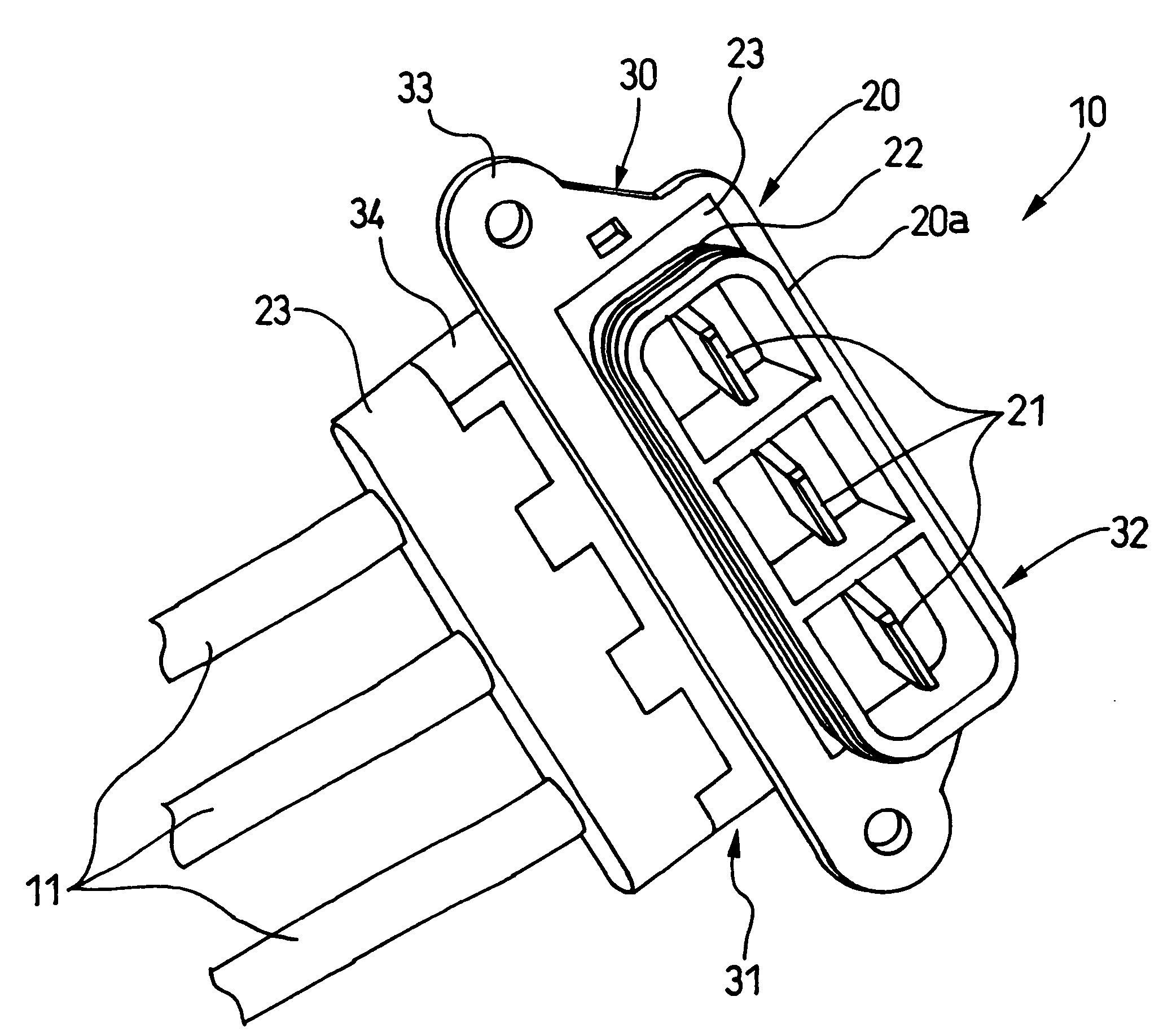
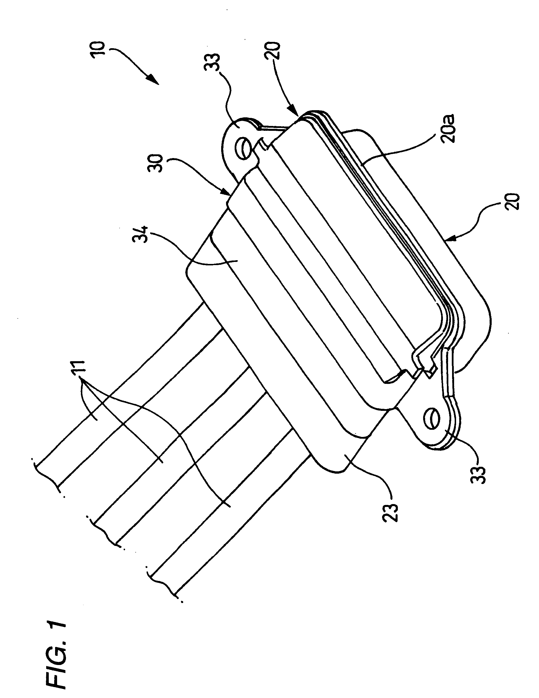
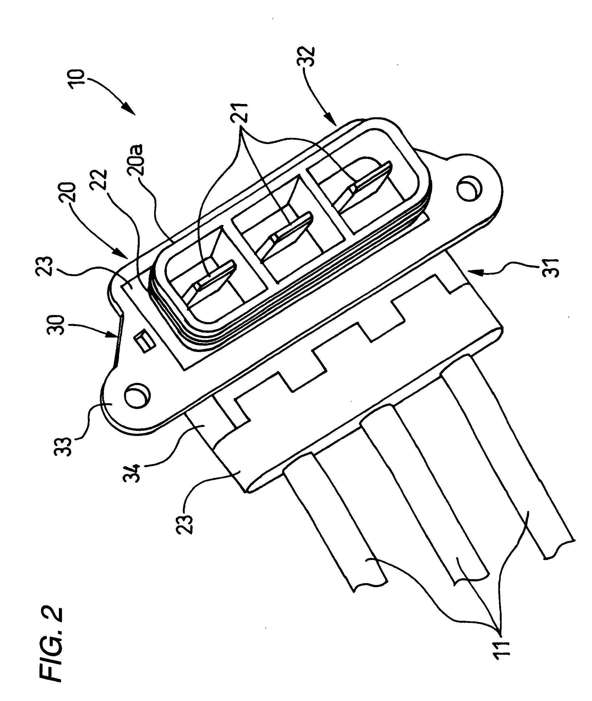
[0044]An embodiment according to the present invention will hereinafter be described in detail with reference to the accompanying drawings. FIG. 1 is a perspective view of an electromagnetic interference shielded connector according to an embodiment of the present invention as seen from above; FIG. 2 is a perspective view of the electromagnetic interference shielded connector as seen from below; FIG. 3 is a perspective view of a shielding shell as seen from above; FIG. 4 is a perspective view of the shielding shell as seen from below; FIG. 5 is a cross-sectional view showing the front end and a mounting portion of the electromagnetic interference shielded connector; FIG. 6 is an enlarged cross-sectional view showing the part VI in FIG. 5; FIG. 7 is an enlarged cross-sectional view showing the part VII in FIG. 5; FIG. 8 is a perspective view of a female connector; and FIG. 9 is a perspective view showing a state where the electromagnetic interference shielded connector is mounted on ...


PUM


Abstract

An electromagnetic interference shielded connector includes a plurality of electric wires, which has connecting parts at ends of the electric wires respectively; a connector housing, which contains the electric wires and the connecting parts; and a metallic shielding shell. The metallic shielding shell includes a cylindrical electric-wire drawn-out portion, through which the electric wires are drawn out; and a terminal drawn-out portion, from which the connecting parts are protruded. The connector housing is formed by an entire molding so as to fill a resin inside of the metallic shielding shell in a state that the electric wires are inserted through the electric-wire drawn-out portion and the connecting parts are drawn out through the terminal drawn-out portion.

Description

BACKGROUND OF THE INVENTION[0001]The present invention relates to an electromagnetic interference shielded connector adapted to be attached to front ends of a plurality of electric wires and to be mounted directly on a wall part of a device and method for assembling the same.[0002]There have been disclosed related electromagnetic interference shielded connectors adapted to be attached to a front end of an electric wire (refer to JP-A-7-193966 (FIG. 1), for example).[0003]In an electromagnetic interference shielded connector 100 as shown in FIG. 10, an insulating coating (sheath) 102 is peeled off at a front end of an electric wire 101, and a metallic reticulated wire (shielding braid) 103 is folded back toward the side of the sheath 102, while a core 104 is extended out of the terminal.[0004]Around the circumference of the folded shielding braid 103 is tightened a metallic pressure contactor 110 in such a manner that an outer cylindrical portion 110a is tightened around the circumfe...

Claims


Application Information

Patent Timeline
Patent Type & Authority Patents(United States)
IPC IPC(8): H01R13/648H01R13/405H01R13/52H01R13/658H01R13/6589H01R43/24
CPCH01R13/6589H01R43/24
Inventor FUKUSHIMA, HIROTAKATSUKAMOTO, TAKASHI
Owner YAZAKI CORP
Why Eureka
Try Eureka