Image processing apparatus and recording medium, and image processing apparatus
Inactive Publication Date: 2007-01-23
SEIKO EPSON CORP
View PDF14 Cites 27 Cited by
Summary
Abstract
Description
Claims
Application Information
AI Technical Summary
This helps you quickly interpret patents by identifying the three key elements:
Problems solved by technology
Method used
Benefits of technology
[0053]According to (4), (9) or (12), luminance is calculated based on the digital data, and the smoothing intensity is calculated using the luminance. The filter information is selected based on the smoothing intensity and the edge information. Thus, the smoothing intensity can be changed using the luminance of the edge, and noise near the edge can be extensively removed. As a result, the noise near the edges can be removed without emphasizing the noise present in the flat portions.
[0054]According to (5), (10) or (13), digital data is smoothed by us
Problems solved by technology
This unwanted electrical signal is included as noise in the digital data constituting an image.
However, according to the method (a) for smoothing the image data or for emphasizing the contours in accordance with the slopes of the edges, noise present in a flat portion wherein the amount of noise is comparatively less is also emphasized, and the image quality is deteriorated.
Therefore, it is difficult to perform fast processing such as pi
Method used
Image
Click on the blue label to locate the original text in one second.
Reading with bidirectional positioning of images and text.
Examples
first embodiment
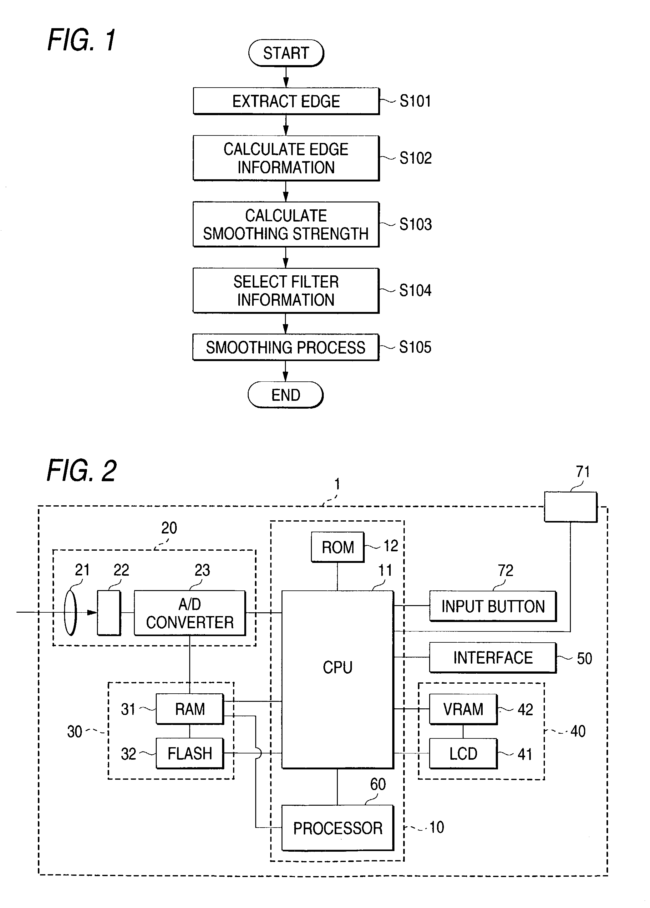
[0068]FIG. 2 is a diagram showing a digital camera 1 for which an image processing apparatus according to a first embodiment of the present invention is applied.
[0069]As is shown in FIG. 2, the digital camera 1 comprises: a controller 10, an image input unit 20, a recording unit 30, a display unit 40 and an interface 50.
[0070]The controller 10 is an electric circuit for processing digital data output by the image input unit 20. The controller 10 includes a CPU (Central Processing Unit) 11, a ROM (Read Only Memory) 12 and a processor 60. In the ROM 12, a computer program is recorded that is executed by the CPU 11 and the processor 60 of the controller 10.
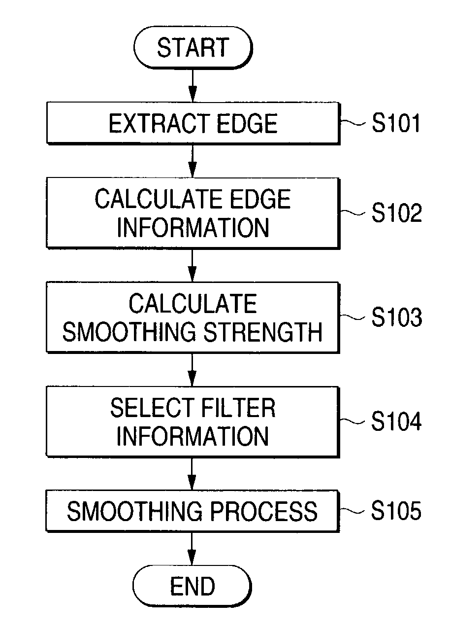
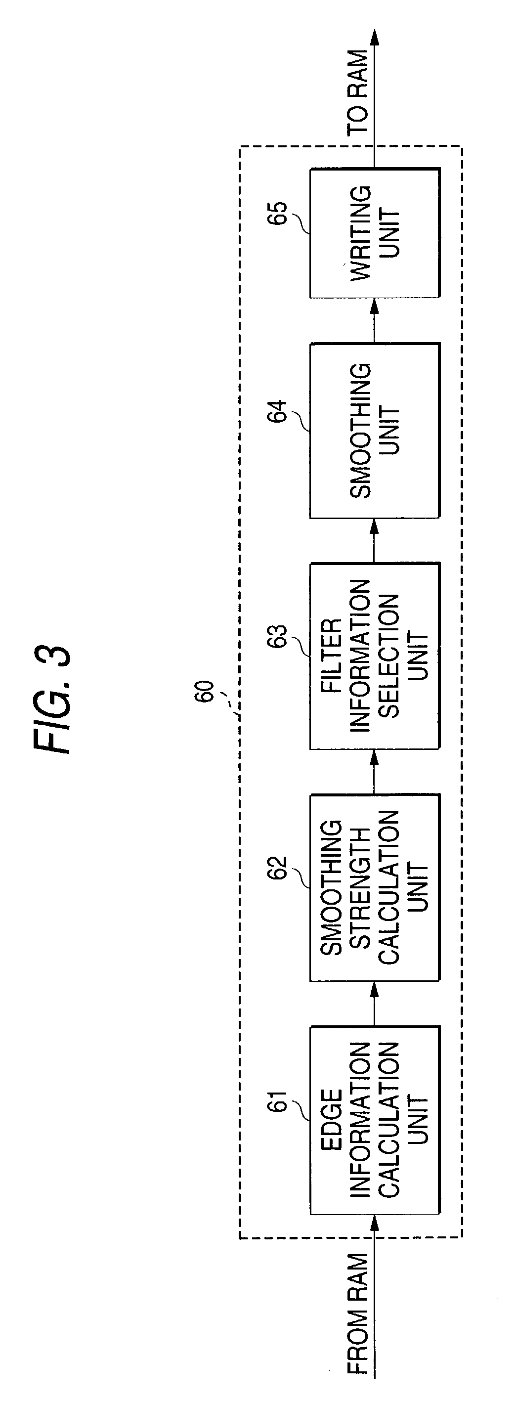
[0071]As is shown in FIG. 3, the processor 60 includes an edge information calculation unit 61, a filter information selection unit 63, a smoothing unit 64 and a writing unit 65.
[0072]As is shown in FIG. 2, an input unit for receiving an entry from a user is connected to the controller 10. The input unit includes a shutter button 71 ...
second embodiment
[0128]A processor 100 for a digital camera according to a second embodiment of the present invention will now be described while referring to FIGS. 10 and 11. No explanation will be given for components and processing that are substantially the same as those in the first embodiment.
[0129]The second embodiment differs from the first embodiment in that filter information is generated each time the grade grad of the slope of the edge and the direction θg of the slope, both of which constitute the edge information.
[0130]As is shown in FIG. 11, the processor 100 for the digital camera in the second embodiment comprises: an edge information calculation unit 101, a smoothing strength calculation unit 102, a filter information generation unit 103, a smoothing unit 104 and writing unit 105.
[0131]The edge information calculation unit 101 and the smoothing strength calculation unit 102 are the same as those in the first embodiment. The filter information generation unit 103 generates filter in...
PUM
Abstract
The edge of an image is extracted, and edge information that includes the grade and the direction of the slope of the edge is obtained. The smoothing strength is calculated using the luminance of a pixel, and filter information is selected from the obtained edge information and the obtained smoothing strength. Then, digital data is smoothed by using the selected filter information. Since the filter information is set in advance, a fast smoothing process is implemented by selecting appropriate filter information. Further, the information for a smoothing range describes an elliptical shape when the slope is large, and the smoothing range is inclined in accordance with the direction of the slope. Therefore, noise near the edge can be thoroughly removed.
Description
[0001]This is a continuation of Application No. PCT / JP01 / 05915 with an international filing date of Jul. 6, 2001, which was published under PCT Article 21(2) in Japanese, and the complete disclosure of which is incorporated into this application by reference.BACKGROUND OF THE INVENTION[0002]The present invention relates to an image processing method, a recording medium, and an image processing apparatus for smoothing digital data for an input image and for removing noise.[0003]For an image input device such as a digital still camera (hereinafter referred to as digital cameras) or a scanner that use image input unit, including a CCD, the image input unit sometimes outputs not only an electric signal corresponding to the intensity of the light received, but also an unwanted electric signal. This unwanted electrical signal is included as noise in the digital data constituting an image. The occurrence of this noise tends to be especially remarkable in a low intensity luminous portion, i...
Claims
Application Information
Patent Timeline
Application Date:The date an application was filed.
Publication Date:The date a patent or application was officially published.
First Publication Date:The earliest publication date of a patent with the same application number.
Issue Date:Publication date of the patent grant document.
PCT Entry Date:The Entry date of PCT National Phase.
Estimated Expiry Date:The statutory expiry date of a patent right according to the Patent Law, and it is the longest term of protection that the patent right can achieve without the termination of the patent right due to other reasons(Term extension factor has been taken into account ).
Invalid Date:Actual expiry date is based on effective date or publication date of legal transaction data of invalid patent.