Memory module and memory-assist module

a memory module and memory-assist technology, applied in the field of memory modules and memory-assist modules, to achieve the effect of effective us

Inactive Publication Date: 2007-01-23
BUFFALO CORP LTD
View PDF10 Cites 38 Cited by
  • Summary
  • Abstract
  • Description
  • Claims
  • Application Information

AI Technical Summary

Benefits of technology

[0009]The present invention is achieved for solving the above-described problem. An object of the present invention is to provide a memory module and memory-assist module for permitting a computer body to access a memory area which cannot be accessed using only a predetermined number of address signals inputted from the computer body so that the memory area is effectively used.

Problems solved by technology

Also with the module of Japanese Patent No.3022255, memories to be accessed are only switched according to the most significant address signal A11, so that this module had the same problem.

Method used


Image

  • Memory module and memory-assist module
  • Memory module and memory-assist module
  • Memory module and memory-assist module

Examples


Embodiment Construction

[0054]Embodiments of the present invention is explained in the following order.

[0055](1) Structure of a memory module

[0056](2) Effect of the memory module

[0057](3) Alternatives

[0058](1) Structure of a Memory Module

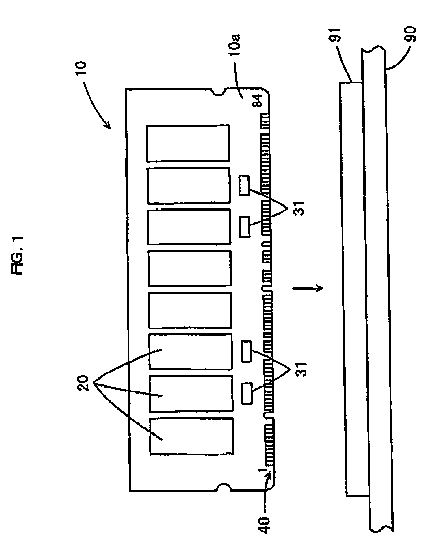
[0059]FIG. 1 is a front view showing an appearance of a memory module 10 of an embodiment of the present invention. The positional relationship of up, down, left, and right is explained according to FIG. 1.

[0060]Eight 256-megabit SDRAMs 20, a plurality of gate ICs 31, a resistor circuit (not shown), and the like are mounted on a print board 10a of the memory module 10. The print board 10a has a standardized shape. A 168-pin DIMM terminal 40 is formed on the bottom edge of the print board 10a. Each of front and back surfaces of the bottom edge has 84 pins. The memory module 10 is an expansion memory card for desktop type personal computers (PCs), and can be inserted to a connector (slot) 91 of a mother board 90 of a desktop type PC (computer body). Corresponding to location...


PUM


Abstract

A computer body outputting a predetermined number of address signals A0 to A11 and a plurality of select signals CSO and CSI, generates a memory select signal CS and an additional address signal A12 added to the signals A0 to A11 according to the inputted signals CSO and CSI, and provides the signal CS, signal A12, and signals A0 to AI1 to a 256-megabit SDRAM (memory), so that the computer body can access the corresponding data. The computer body can access the data corresponding to the generated additional address signal A12 and predetermined number of the address signals A0 to A11.

Description

BACKGROUND OF THE INVENTION[0001]1. Field of the Invention[0002]The present invention relates to a memory module and memory-assist module connectable to a computer body.[0003]2. Description of the Prior Art[0004]Conventionally, memory expansion has been implemented by connecting memory modules to sockets (slots) of a computer body. As the memory modules, a 128-megabyte DIMM (Dual Inline Memory Module) having eight 128-megabit SDRAMs (Synchronous Dynamic Random Access Memories), a 128-megabyte DIMM (Dual Inline Memory Module) having sixteen 256-megabit SDRAMs (Synchronous Dynamic Random Access Memories), and the like are used. Generally, twelve address signal terminals A0 to A11 are provided to the 128-megabit SDRAM, to which twelve signal lines of a row address and ten signal lines of a column address can be connected. When address signals A0 to A11 are inputted from the computer body, data of an address corresponding to the address signals can be read / written from / on the whole 128-...

Claims


Application Information

Patent Timeline
Patent Type & Authority Patents(United States)
IPC IPC(8): G06F12/00G11C7/00G11C5/00G11C5/06G06F12/06G11C7/10G11C11/408
CPCG06F12/0623G11C5/04G11C11/408G11C7/1072G11C2207/2227G11C2207/105
Inventor BUNGO, MOTOHIKOYUASA, KAORU
Owner BUFFALO CORP LTD
Why Eureka
Try Eureka