Method for manufacturing single-sided hard memory disks

a hard memory disk and manufacturing method technology, applied in the field of processing hard memory disks, can solve the problems of difficult and expensive employment, active materials and manufacturing processes, and the technology used to manufacture hard memory disks has rapidly advanced, and achieve the effect of increasing production outpu

Inactive Publication Date: 2007-01-30
MAXTOR
View PDF72 Cites 10 Cited by
  • Summary
  • Abstract
  • Description
  • Claims
  • Application Information

AI Technical Summary

Benefits of technology

[0030]These and other benefits are addressed by the various embodiments and configurations of the present invention. For example, the benefit provided by the present invention is an increased output in the production of finished disks using conventional double-sided disk manufacturing processes, but with multiple pairs of single-sided disks. A cassette is provided which positions the disks in pairs in a gap merg

Problems solved by technology

Although the active materials and manufacturing processes, by their nature, are difficult and expensive to employ, over the years, the technology used to manufacture hard memory disks has rapidly progressed.
Consumers thus are forced to pay substantial amounts for excess storage c

Method used


Image

  • Method for manufacturing single-sided hard memory disks
  • Method for manufacturing single-sided hard memory disks
  • Method for manufacturing single-sided hard memory disks

Examples


first embodiment

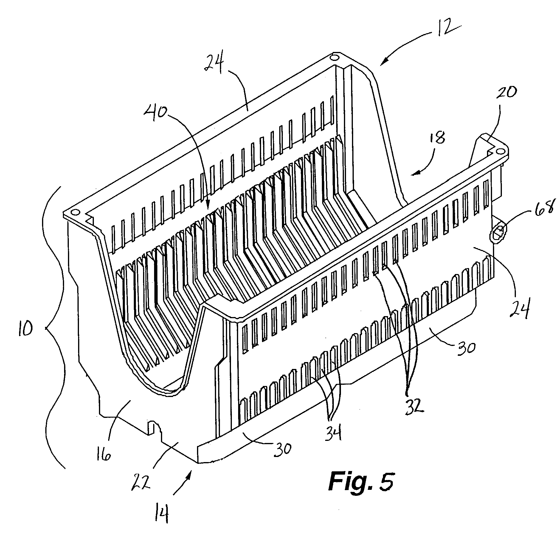
[0057]Turning to FIGS. 6, 10, 11, 14 and 15, the inside surface 36 of the upper and lower portions 26, 28 of the side walls 24 comprise at least one row of grooves 38 for positioning disks in pairs and in gap merge orientation. The grooves may be formed by recessing channels in the side walls or by extending ribs or ribs 40 from the side walls, or perhaps by both. In the first embodiment, designed for pairs of gap merge disks, the ribs 40 alternate between large and small raised ribs 42, 44, respectively. The larger ribs 42 are disposed between and separate disk pairs. The larger ribs 42 have side walls 46 formed by two surfaces 48 and 50 joined at an obtuse angle. The side walls 46 merge to form a ridge 52. A single small rib 44 is disposed between consecutive large ribs 42. Like the large ribs, the small ribs also have side walls 54 formed by two surfaces 56, 58 joined at an obtuse angle. Surfaces 56 merge to form a raised ridge 60. The small ribs maintain the separation between t...

second embodiment

[0062]In a second embodiment, shown in FIGS. 17–20, the cassette is also configured for concentric contact merge orientation of disks. This particular embodiment is designed for use in the sputtering process. It is shorter in height than the embodiment shown in FIGS. 5–16, and is preferably made from metal to accommodate the elevated disk temperatures resulting from the high temperatures of the sputtering process. The cassette may be die cast or stamped. Due to the possible application in high temperature environments, appropriate metals include 304 or 316 stainless steel or aluminum, which can maintain integrity in high temperature environments and when holding high temperature disks. Although the temperatures in the sputtering chambers may reach 350 degrees Celsius, the disk temperatures in the cassettes do not typically exceed 270 degrees Celsius.

[0063]The cassette 80 has two side walls 82, two end walls 84, an open top 86 and an open bottom 88. The end walls have a U-shaped or s...


PUM

PropertyMeasurementUnit
Lengthaaaaaaaaaa
Lengthaaaaaaaaaa
Lengthaaaaaaaaaa

Abstract

Various apparatus and methods are provided for positioning and handling single-sided hard memory disks. A disk carrier is provided with ribs formed on the inside surface of opposing side walls. The ribs form disk receiving grooves or channels. The ribs further comprise an alternating pattern of large and small ribs. The large ribs separate pairs of disks from other pairs, the small ribs separate and maintain spacing of the two disks comprising each pair of disks.

Description

CROSS REFERENCE TO RELATED APPLICATION[0001]Priority is claimed from U.S. Provisional Patent Application Ser. No. 60 / 417,632 filed Oct. 10, 2002, which is incorporated by reference herein in its entirety.[0002]The subject matter of the present application is related to the following applications, each of which has a filing date of May 9, 2003: application Ser. No. 10 / 434,550 entitled Single-Sided Sputtered Magnetic Recording Disks to Clasara et al. (Publication No. US-2003-0211361-A1); application Ser. No. 10 / 435,361 entitled Dual Disk Transport Mechanism Processing Two Disks Tilted Toward Each Other to Grow et al. (Publication No. US-2003-0208899-A1); application Ser. No. 10 / 435,358 entitled Information-Storage Media With Dissimilar Outer Diameter and / or Inner Diameter Chamfer Designs On Two Sides to Clasara et al. (Publication No. US-2003-0210498-A1); application Ser. No. 10 / 435,360 entitled Method of Merging Two Disks Concentrically Without Gap Between Disks to Buitron (Publicati...

Claims


Application Information

Patent Timeline
IPC IPC(8): G11B5/127H04R31/00G11B23/00G11B23/50G11B33/04
CPCG11B33/0444Y10S428/922Y10T29/49027Y10T29/47Y10T29/49069Y10T428/21Y10T428/24479Y10T428/2918Y10T29/49025
Inventor BUITRON, GERARDOCROFTON, WALTERHACHTMANN, BRUCENEWMAN, DAVID
Owner MAXTOR
Why Eureka
Try Eureka