Fly reel drag mechanism

a technology of drag mechanism and fly fishing reel, which is applied in the field of drag assembly of fly fishing reel, can solve the problems of increasing the drag force exerted on the spool, reducing the performance of the fishing reel, and multiple, intricate components of the drag mechanism, so as to reduce and increase the rotational frictional force

Inactive Publication Date: 2007-01-30
SHAKESPEARE CO
View PDF29 Cites 26 Cited by
  • Summary
  • Abstract
  • Description
  • Claims
  • Application Information

AI Technical Summary

Benefits of technology

[0005]One embodiment of the present invention provides a fishing reel including a housing having a central hub and a main shaft having a proximal end and a distal end, the main shaft being non-rotatably fixed to the central hub at its proximal end. A spool having a central recess is releasably secured to the main shaft distal end and a one-way clutch having a central bore is non-rotatably received in the central recess. The reel also includes a drag assembly with a drag housing having a drag surface and a central aperture, the drag housing being fixed to the central hub of the housing such that a drag cavity is formed therebetween. A sleeve extends along the main shaft and has a first portion received in the central bore of the one-way clutch and a second portion extending into the drag cavity. A first drag washer is disposed in the drag cavity and non-rotatably fixed to the second portion of the sleeve and a drag knob is rotatably secured to the housing. Rotation of the drag knob in a first direction urges the drag washer axially along the sleeve toward the drag surface and increases rotational frictional force on the first drag washer. Rotation of the drag knob in a second direction reduces rotational frictional force exerted on the first drag washer.
[0006]Another embodiment of the present invention provides a fishing reel including a housing having a central hub and a main shaft having a proximal end and a distal end, the main shaft being non-rotatably fixed to the central hub at the proximal end. A spool is rotatable about the main shaft and releasably secured to the main shaft distal end. A drag housing has a drag surface and a central aperture and is fixed to the central hub of the housing such that a drag cavity is formed therebetween. A sleeve extends along the main shaft and has a first end adjacent the distal end of the main shaft and a second end extending into the drag cavity adjacent to the central hub. A first bearing assembly is disposed between the first end of the sleeve and the distal end of the main shaft and a second bearing assembly is disposed between the second end of the sleeve and the central hub of the housing. A first drag washer is disposed in the drag cavity and is non-rotatably fixed to the sleeve. A drag knob is rotatably secured to the housing such that rotation of the drag knob in a first direction urges the drag washer axially along the sleeve and increases rotational frictional force between the first drag washer and the drag surface of the drag housing. Rotation of the drag knob in a second direction reduces the frictional force exerted on the first drag washer.

Problems solved by technology

Typically, these drag mechanisms include multiple, intricate components that are often exposed to environmental parameters, such as water, salt, etc.
Exposure to such elements over time can lead to the degradation of the individual components, thereby causing reduced performance of the fishing reel.
In addition, these mechanisms frequently operate on the concept of increasing friction between the intricate components, thereby increasing the drag force exerted on the spool.
Increased friction between the intricate elements can also lead to wear of the components, and ultimately degrade the performance of the fishing reel.

Method used


Image

  • Fly reel drag mechanism
  • Fly reel drag mechanism
  • Fly reel drag mechanism

Examples


Embodiment Construction

[0016]It is to be understood by one of ordinary skill in the art that the discussion herein is a description of exemplary embodiments only, and is not intended as limiting of the broader aspects of the present invention, which broader aspects are embodied in the exemplary constructions.

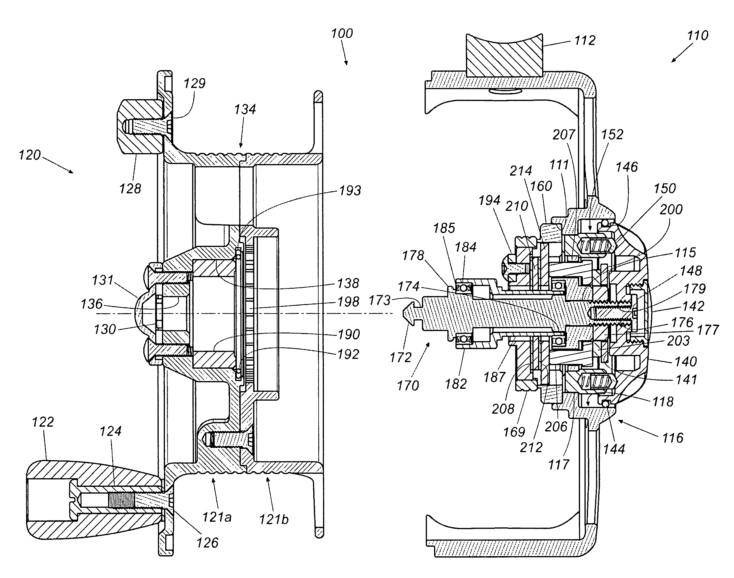
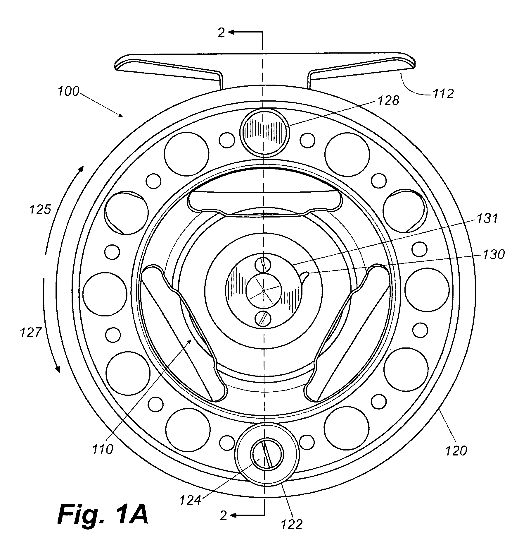
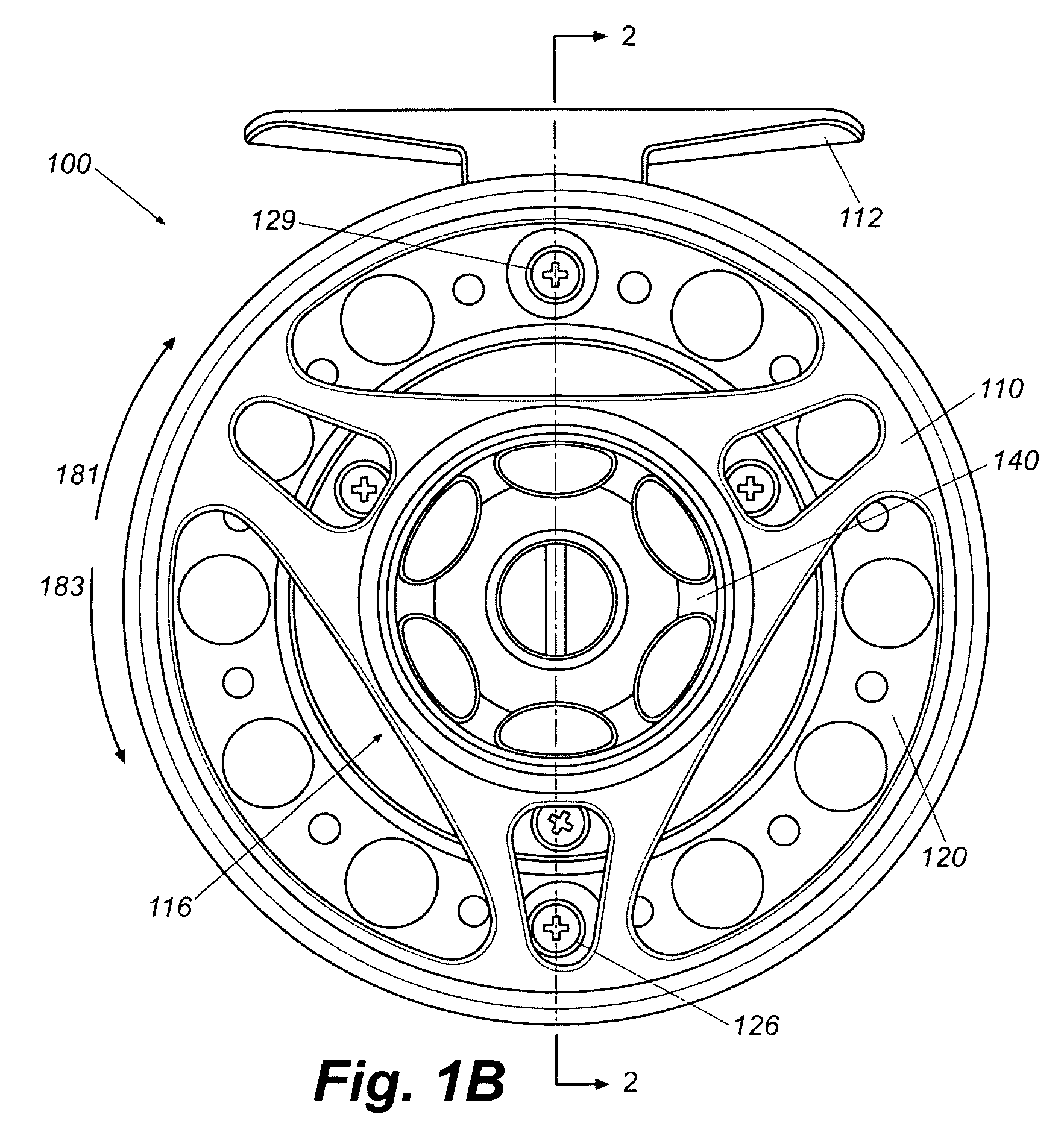
[0017]FIGS. 1A and 1B illustrate a fishing reel 100 constructed in accordance with the present invention. Fishing reel 100 includes a housing 110 and a spool 120. Housing 110 rotatably supports spool 120 and includes a reel foot 112 for attaching fishing reel 100 to a fishing rod (not shown). As shown in FIG. 1B, housing 110 further includes a central hub 116 that rotatably receives a drag knob 140. Drag knob 140 is used to selectively adjust the amount of force required to unwind fishing-line (not shown) from spool 120. This is commonly referred to as adjusting the “drag” of a fishing reel, as discussed in greater detail below.

[0018]Referring now also to FIG. 2, spool 120 includes a handle knob 122, ...


PUM


Abstract

A fishing reel including a housing having a central hub and a main shaft having a proximal end and a distal end, the main shaft being non-rotatably fixed to the central hub at its proximal end. A spool having a central recess is releasably secured to the main shaft distal end and a one-way clutch having a central bore is non-rotatably received in the central recess. The reel also includes a drag assembly with a drag housing having a drag surface and a central aperture, the drag housing being fixed to the central hub of the housing such that a drag cavity is formed therebetween. A sleeve extends along the main shaft and has a first portion received in the central bore of the one-way clutch and a second portion extending into the drag cavity. A first drag washer is disposed in the drag cavity and non-rotatably fixed to the second portion of the sleeve and a drag knob is rotatably secured to the housing. Rotation of the drag knob in a first direction urges the drag washer axially along the sleeve toward the drag surface and increases rotational frictional force on the first drag washer. Rotation of the drag knob in a second direction reduces rotational frictional force exerted on said first drag washer.

Description

TECHNICAL FIELD[0001]The present invention relates generally to fishing reels. More particularly, the present invention relates to a drag assembly for a fly fishing reel.BACKGROUND OF THE INVENTION[0002]Existing fly fishing reels typically have a spool rotatably mounted to a shaft extending outwardly from a central portion of a reel housing. The spool includes a winding drum that allows fishing line to be either paid out or reeled in dependent upon the direction of rotation of the spool about the main shaft of the fishing reel. At times, it is desirable to increase the force required to pay out fishing line, such as when a fish has been hooked, which is commonly referred to as increasing the amount of “drag” on the reel. The desired amount of force required to pay out the fishing line may vary based on a number of factors, such as the weight of the fish on the line. Existing reels often include mechanisms that allow the user of the fishing reel to vary the force required to pay out ...

Claims


Application Information

Patent Timeline
Patent Type & Authority Patents(United States)
IPC IPC(8): A01K89/016A01K89/033
CPCA01K89/033A01K89/016
Inventor KANG, YOUNG
Owner SHAKESPEARE CO
Why Eureka
Try Eureka