
Adjustable angle clamp

a clamping angle and adjustable technology, applied in the direction of clamps, metal-working machine components, metal-working apparatus, etc., can solve the problems of inability to achieve acute or obtuse angles using this design, the basic clamping design that provides linear clamping pressure cannot work, and the method of using the same is typically only useful, etc., to achieve the effect of simple construction and us

Inactive Publication Date: 2007-01-30
SJUTS ERIC +1
View PDF13 Cites 34 Cited by
  • Summary
  • Abstract
  • Description
  • Claims
  • Application Information

AI Technical Summary

Benefits of technology

The present invention is a clamping device that can securely hold objects in various angles. It provides even pressure on mitered joints and can adjust the pressure on angular joints. The device is easy to use and has a simple construction.

Problems solved by technology

The technical problem addressed in this patent text is the need for a clamping device that can securely join opposing objects at various angles with even pressure at the joint formed between them. Previous clamps have limitations in terms of the angle at which they can be used and the amount of pressure they can apply, resulting in weak joints or uneven pressure distribution. The invention described in this patent aims to overcome these shortcomings by providing a novel clamping device capable of securing objects at various angles with a substantially even clamping force at the joint.

Method used


Image

  • Adjustable angle clamp
  • Adjustable angle clamp
  • Adjustable angle clamp

Examples


Embodiment Construction

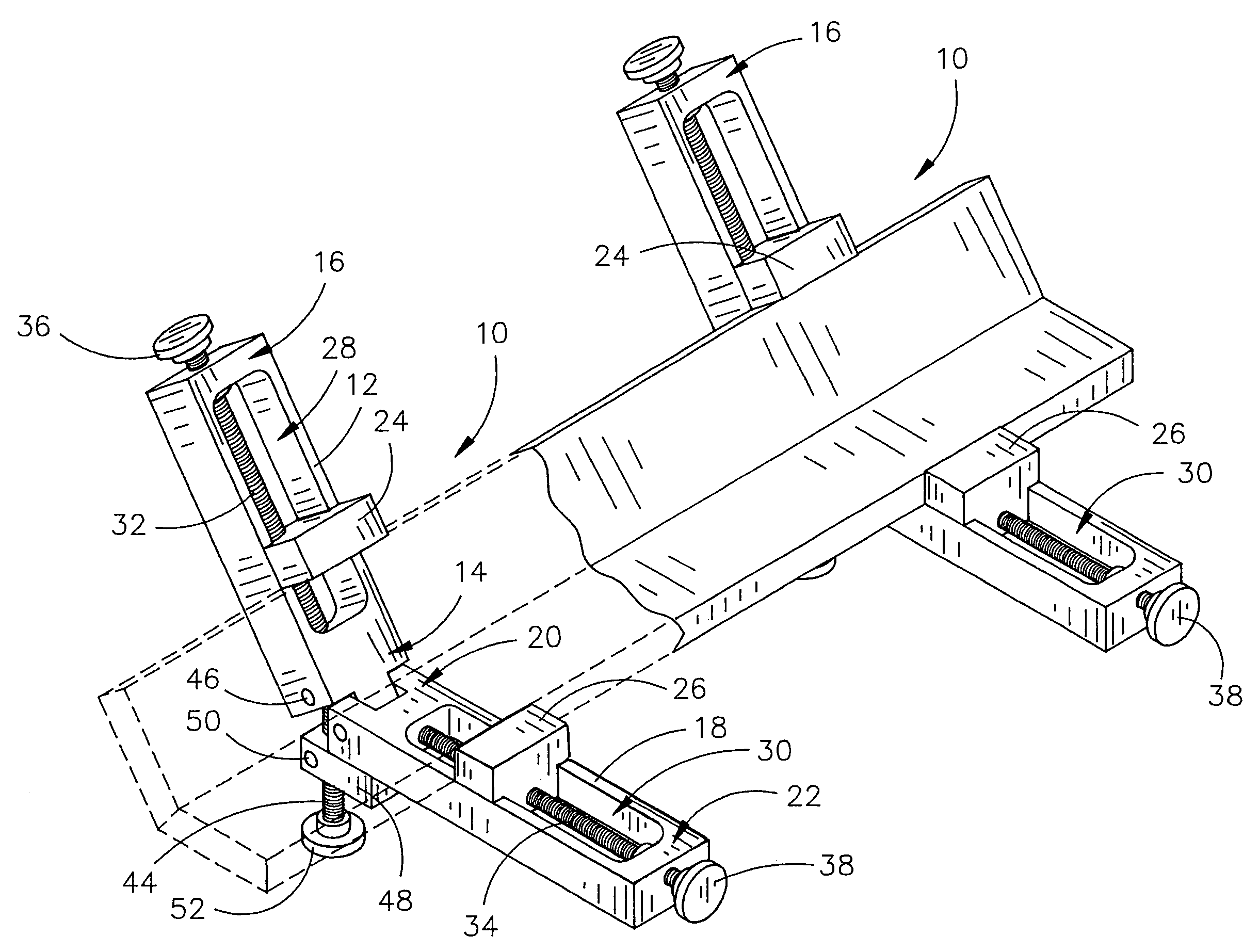
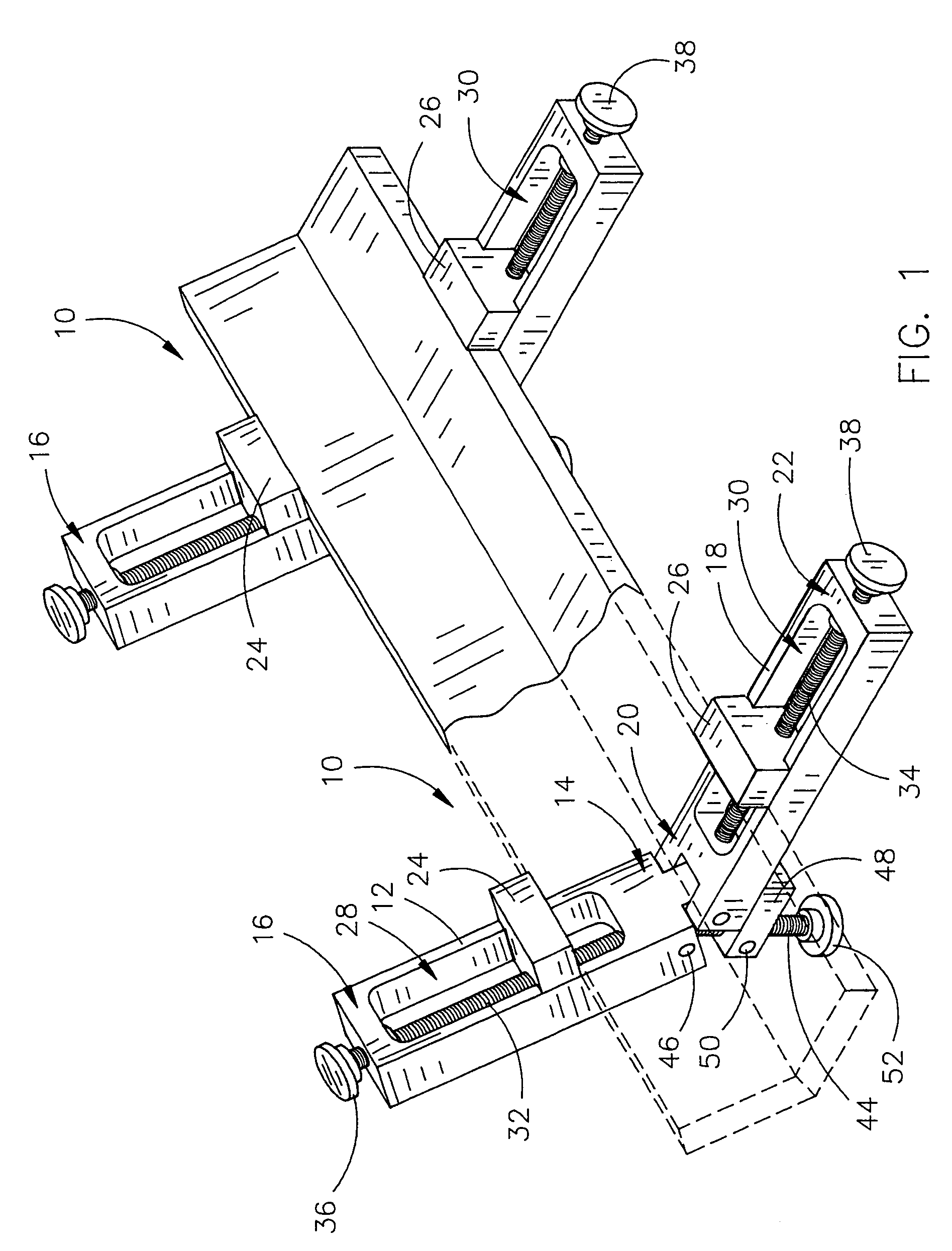
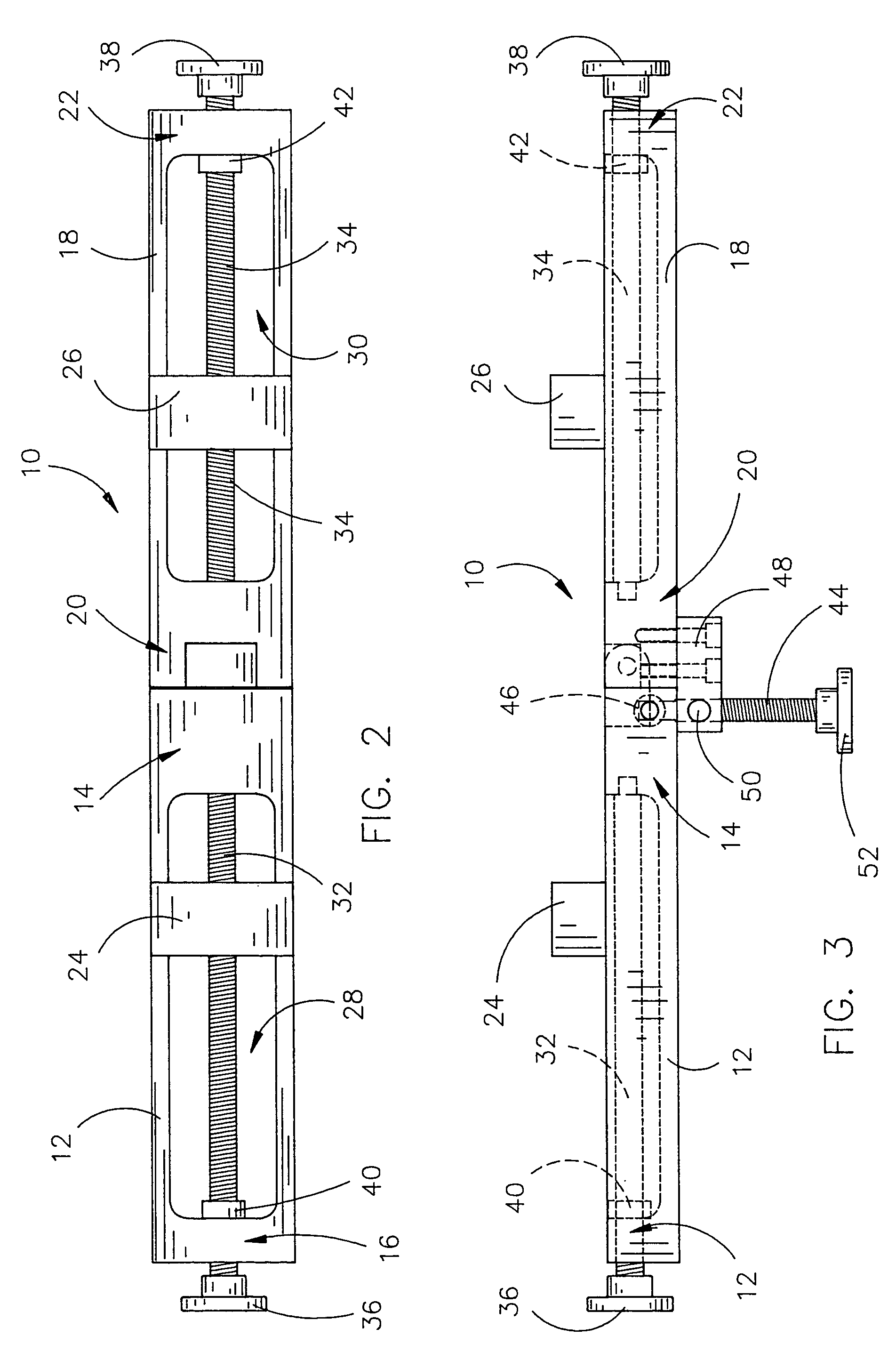
[0020]The angular clamping device 10 of the present invention is generally depicted in one of its preferred embodiments in FIGS. 1–5. While the clamping device 10 will be described herein as the same can be used to clamp opposing pieces of wood to one another, it will be understood by those of skill in the art that the clamping device 10 can be used to clamp opposing objects of nearly any shape or composition to one another for a variety of purposes.

[0021]The clamping device 10 is provided with a first arm member 12, having a length that extends between a first end portion 14 and a second end portion 16. A second arm member is also provided, having a length that extends between a first end portion 20 and a second end portion 22. The first and second arm members 12 and 18 are pivotably coupled to one another at their first end portions 14 and 20 so that they may be selectively moved in variable angular relationships with one another. The clamping device 10 is depicted in FIG. 1 as ha...


PUM


Abstract

The adjustable angle clamp of the present invention is provided with opposing arm members that are pivotably coupled to one another. Jaw members are independently advanced or withdrawn along the lengths of the arm members to provide clamping pressure at a joint formed between opposing objects disposed between the jaws. An angle adjustment screw is coupled to the arm members to incrementally adjust the angular relationship of the arm members with respect to one another and secure the clamp at selected angle settings.

Description


Claims


Application Information

Patent Timeline
Owner SJUTS ERIC
Features
  • Generate Ideas
  • Intellectual Property
  • Life Sciences
  • Materials
  • Tech Scout
  • Unparalleled Data Quality
  • Higher Quality Content
  • 60% Fewer Hallucinations
Learn More