Shortened layout from dryer to reel in tissue machine

Inactive Publication Date: 2007-01-30
METABO PAPER KARLSTAD
View PDF33 Cites 10 Cited by
  • Summary
  • Abstract
  • Description
  • Claims
  • Application Information

AI Technical Summary

Benefits of technology

[0015]The invention in other embodiments also provides a composite shaftless core that can be used in place of the steel core shaft and paper core conventionally used for winding paper. The composite shaftless core can be constructed of a fiber-matrix composite material and advantageously includes metal bushings or fittings at the ends for connection with chucks and/or drive units. The metal fittings may include teeth or splines for engagement by drive units. Th

Problems solved by technology

In the production of high-quality tissue, machine speed and efficiency are often limited by the performance of the dry end of the machine between the final dryer and the winding station or reel-up.
Tissue is extremely delicate and difficult to handle, especially at high machine speeds.
As the machine speed is continually pushed higher and higher in an effort to improve productivity, it becomes increasingly difficult to move the tissue web from the dryer to the reel-up without encountering handling problems.
In many tissue machines, the free draw tends to be quite long, which exacerbates the problem of handling the web.
The conventional type of tissue machine described above has a number of drawbacks that limit the machine speed

Method used


Image

  • Shortened layout from dryer to reel in tissue machine
  • Shortened layout from dryer to reel in tissue machine
  • Shortened layout from dryer to reel in tissue machine

Examples


Example

DETAILED DESCRIPTION OF THE DRAWINGS

[0044]The present invention now will be described more fully hereinafter with reference to the accompanying drawings, in which preferred embodiments of the invention are shown. This invention may, however, be embodied in many different forms and should not be construed as limited to the embodiments set forth herein; rather, these embodiments are provided so that this disclosure will be thorough and complete, and will fully convey the scope of the invention to those skilled in the art. Like numbers refer to like elements throughout.

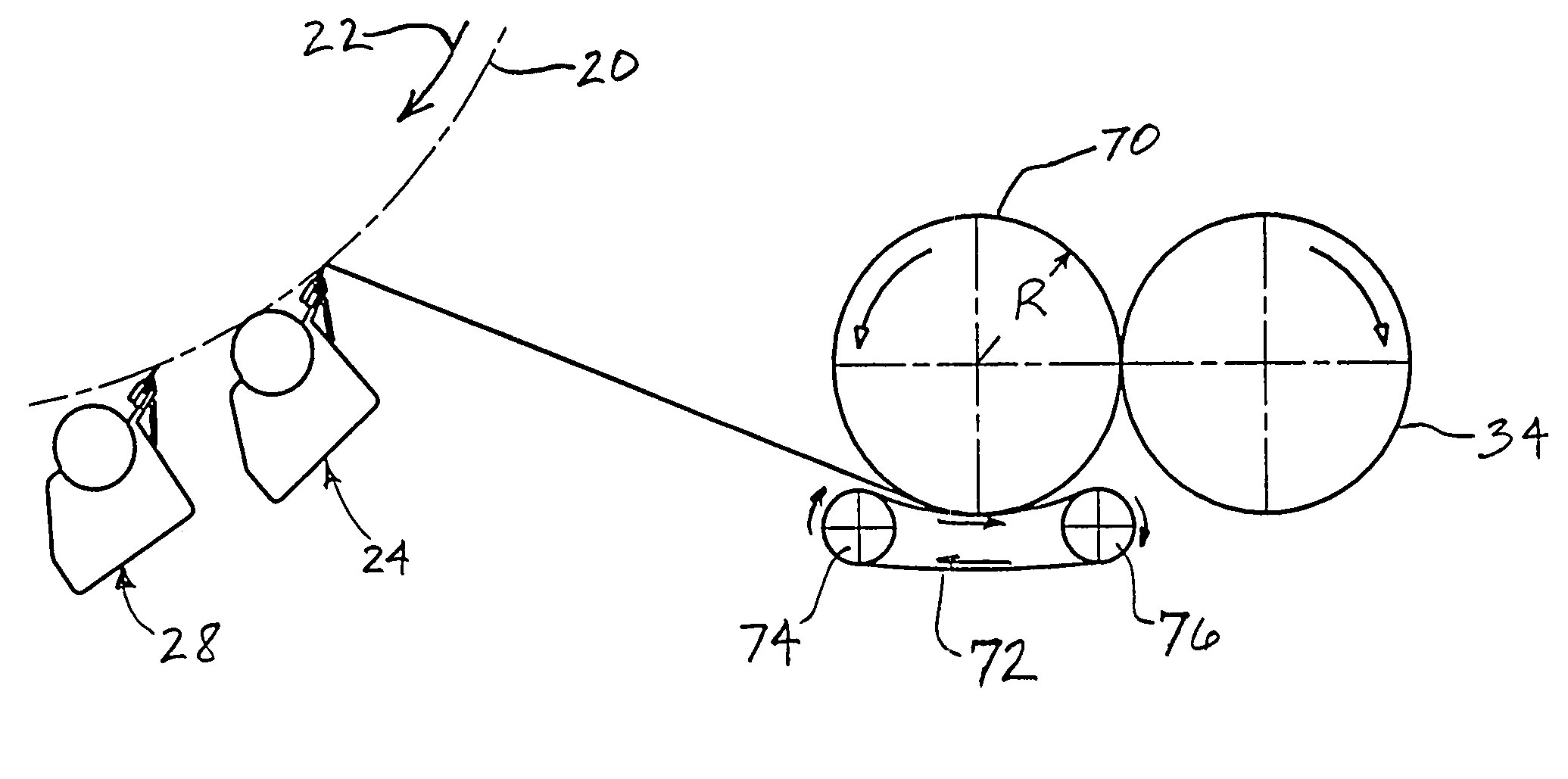
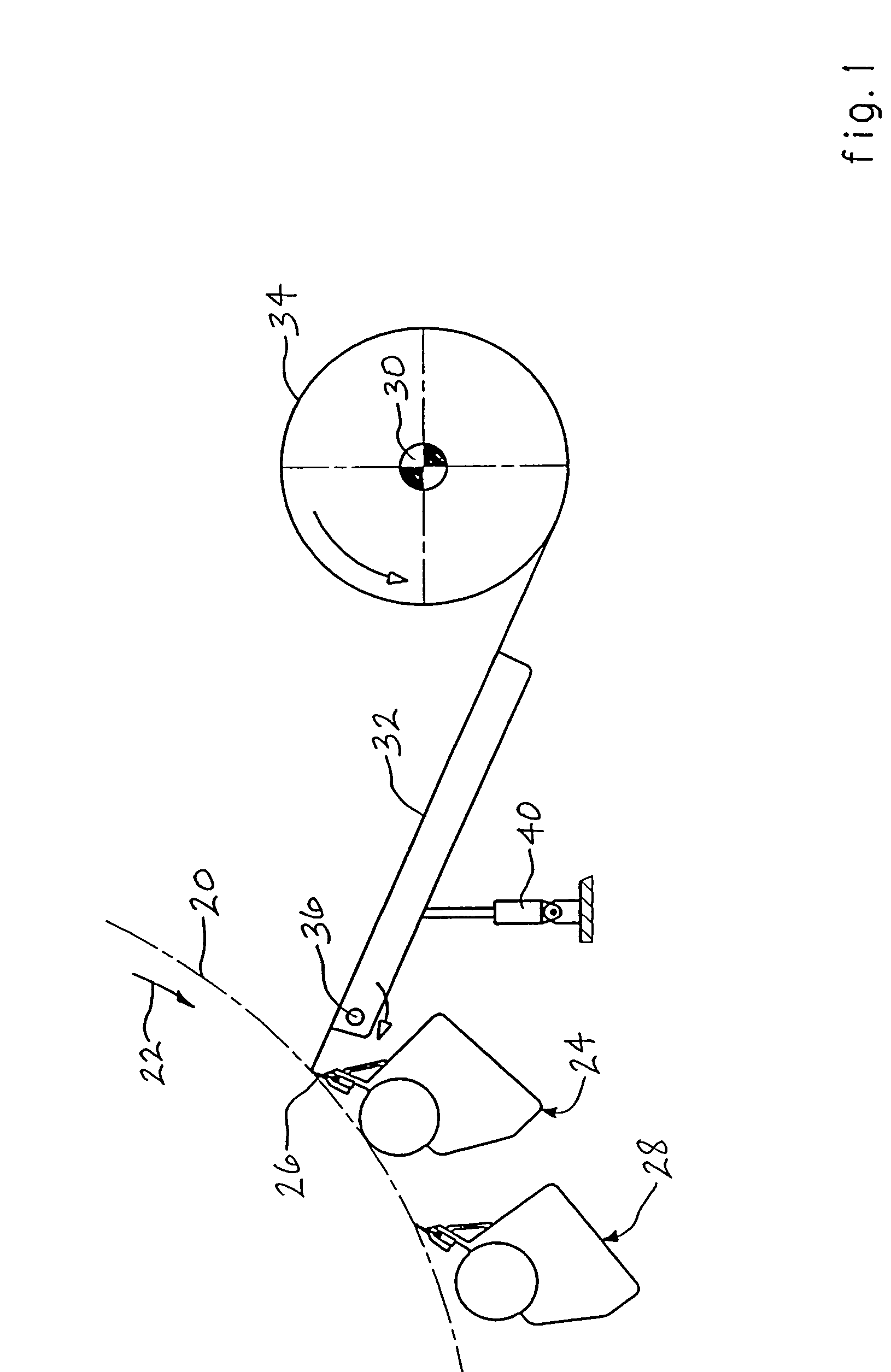
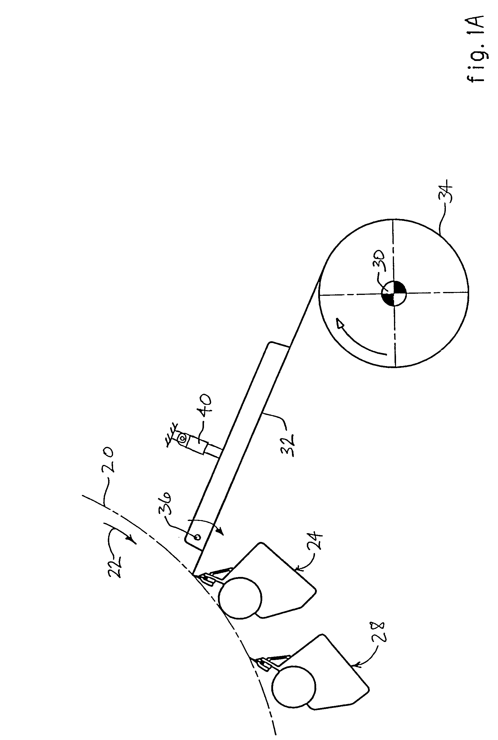
[0045]FIGS. 1 and 1A depict the dry end of a papermaking machine in accordance with a first pair of related embodiments of the invention. The paper web, as is conventional, is dried on a Yankee dryer having a heated dryer roll 20 rotating in the direction of arrow 22. The web is removed from the roll 20 and preferably creped by a creping doctor 24 having a doctor blade 26. A cleaning doctor 28 arranged after the creping ...


PUM

PropertyMeasurementUnit
Stabilityaaaaaaaaaa
Tensionaaaaaaaaaa

Abstract

A dry end of a tissue machine is made shorter by close-coupling a reel-up to the drying section and supporting the web from the drying section to the reel-up by a foil or a belt such that web stability is maintained, thus allowing high-speed operation. The foil's downstream edge can form a nip with the paper roll and nip load can be controlled by controlling pivotal movement of the foil. The reel-up can include a calendering belt for calendering the web as it passes through a nip between the belt and a reel drum supported on the belt, and a rotatable reel spool on which a paper roll is wound in nipping engagement with the reel drum. Alternatively, the reel drum can be eliminated and the paper roll can be supported on the belt. A composite shaftless core for winding is also disclosed.

Description

CROSS-REFERENCE TO RELATED APPLICATIONS[0001]The present application is a divisional of U.S. application Ser. No. 09 / 882,659, now U.S. Pat. No. 6,669,818, filed Jun. 15, 2001, which claims the benefit of the filing date of U.S. Provisional Application No. 60 / 214,507, filed Jun. 28, 2000.FIELD OF THE INVENTION[0002]The invention relates to papermaking machinery and methods. The invention relates more particularly to improvements in the dry end of a tissue machine enabling a close coupling between a dryer and a reel-up where the finished paper web is wound into a roll and enabling improved control of nip load in the reel-up.BACKGROUND OF THE INVENTION[0003]In the production of high-quality tissue, machine speed and efficiency are often limited by the performance of the dry end of the machine between the final dryer and the winding station or reel-up. Tissue is extremely delicate and difficult to handle, especially at high machine speeds. As the machine speed is continually pushed high...

Claims


Application Information

Patent Timeline
IPC IPC(8): D21F5/02D21F11/00D21G1/00B65H18/10B65H18/02B65H18/14B65H18/26B65H75/10B65H75/18B65H75/28D21F3/00D21F5/00D21F11/14D21G9/00
CPCB65H18/02D21G9/0063B65H18/26B65H75/10B65H75/185B65H75/28D21F3/00D21F5/00D21F11/14D21F11/145B65H18/14B65H2301/41346B65H2301/41366B65H2301/41376B65H2301/41426B65H2301/41816B65H2301/41818B65H2401/112B65H2701/5122B65H18/08
Inventor LINDEN, ANDERS TOMMY
Owner METABO PAPER KARLSTAD
Why Eureka
Try Eureka