Microplate liquid handling system

Inactive Publication Date: 2007-01-30
HITACHI KOKI CO LTD
View PDF11 Cites 22 Cited by
  • Summary
  • Abstract
  • Description
  • Claims
  • Application Information

AI Technical Summary

Benefits of technology

[0011]It is therefore an object of the present invention to provide a microplate liquid handling system requiring a minimum instal

Problems solved by technology

That is, a large installation place is required.
Further, a critical error may occur in the test results due to attachment of the row of dispensing tips to an erroneous row of the nozzles.
This requires a large amount of sample or reagent, which is valuable in itself, resulting in a marked deterioration in test efficiency.
H

Method used


Image

  • Microplate liquid handling system
  • Microplate liquid handling system
  • Microplate liquid handling system

Examples


Example

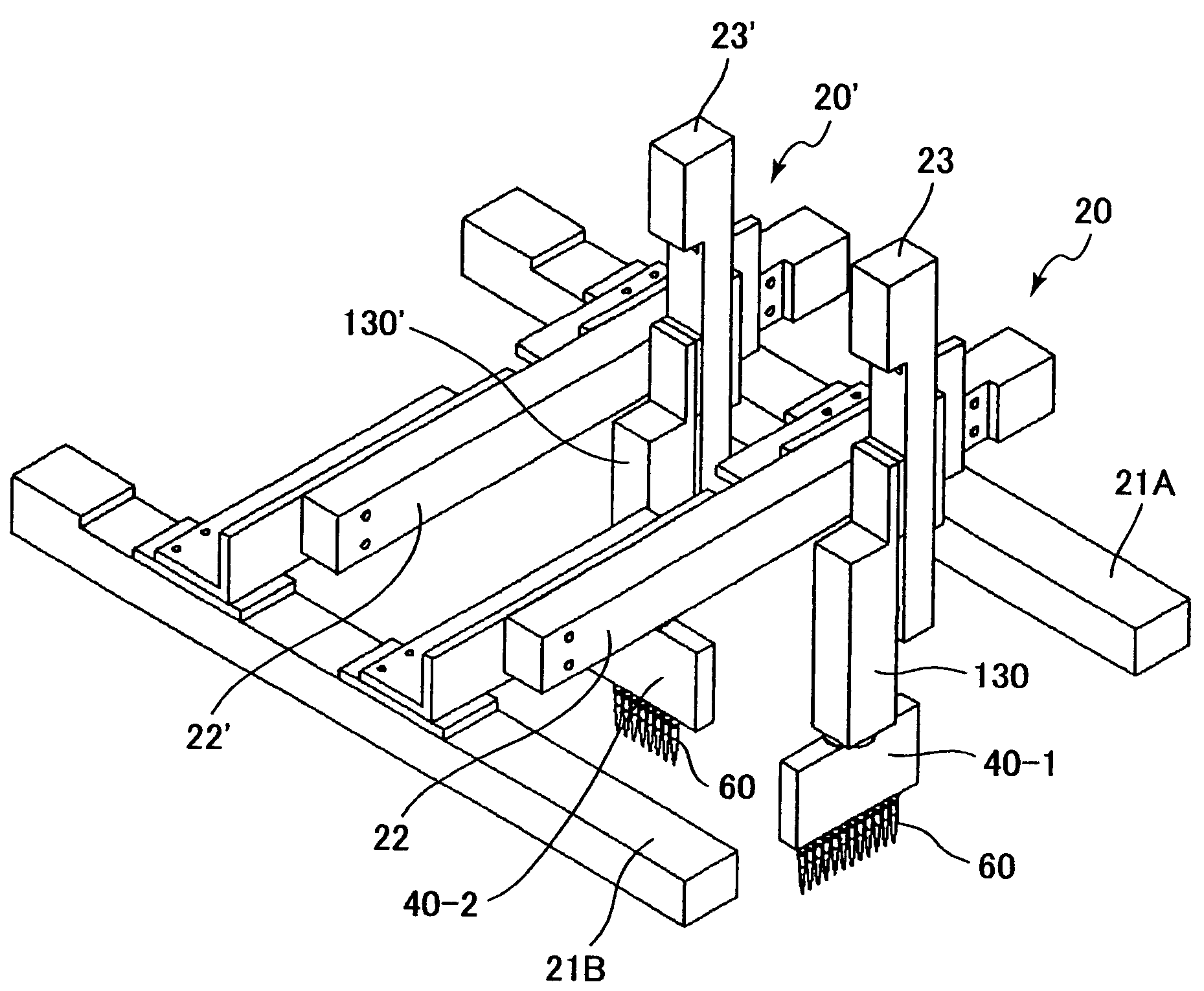
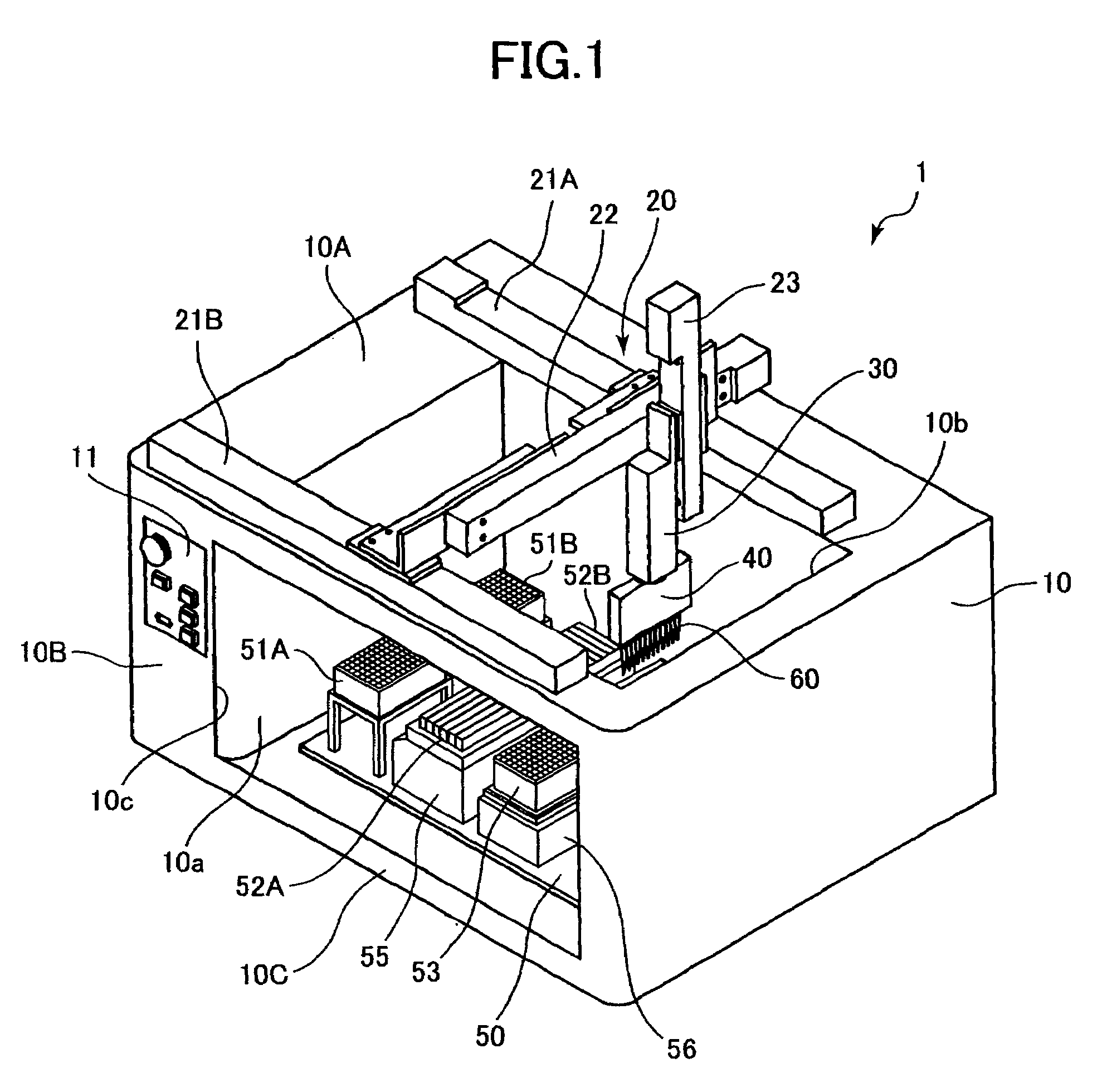
[0023]A microplate liquid handling system according to a first embodiment of the present invention will now be described with reference to FIGS. 1 through 5. A microplate liquid handling system 1 has a main body 10, which is equipped with a moving mechanism 20, a rotating mechanism 30, a dispensing mechanism 40, and a stage 50. The main body 10 has a substantially rectangular box-like outward configuration, and defines therein a substantially rectangular chamber 10a which is substantially geometrically similar to the outward configuration of the main body 10. Partially formed in an upper surface 10A and a front surface 10B of the main body 10 are openings 10b and 10c outwardly open from within the chamber 10a. The openings 10b and 10c have rectangular configurations which are respectively substantially geometrically similar to those of the upper surface 10A and the front surface 10B. The stage 50 is provided on an inner peripheral surface defining the chamber 10a, on a bottom surfac...

Example

[0064]Next, a microplate liquid handling system according to a second embodiment of the present invention will be described with reference to FIGS. 6 and 7. The microplate liquid handling system of the second embodiment only differs from that of the first embodiment in that the rotating mechanism is equipped with a pulley 48 and an abutment member 12 instead of the stepping motor 32. The dispensing mechanism 40 is rotated by the pulley 48 and the abutment member 12.

[0065]More specifically, in a portion of the dispensing mechanism 40 and at the position where the cylinder retaining portion 41 and the supported portion 42′ are connected, there is provided a disc-shaped pulley 48. The axis of the pulley 48 is in alignment with the rotation axis of the dispensing mechanism 40, and the pulley 48, the cylinder retaining portion 41, and the supported portion 42′ are integrally rotatable.

[0066]Further, the abutment member 12 in the form of a rectangular plate is provided in the inner periph...


PUM


Abstract

A microplate liquid handling system requiring minimum installation area, helping to avoid waste of various reagents, and making it possible to perform dispensing the various reagents in the shortest possible time. The microplate liquid handling system has a main frame body provided with a moving mechanism, a dispensing mechanism, and a stage. On the stage, a microplate, two dispensing tip containers, and two reagent vessels are mounted. Formed in the microplate are 12×8 wells, i.e., 96 wells in total, arranged in matrix. The microplate, the dispensing tip containers, and the reagent vessels are substantially of the same, rectangular configuration. Each of the two dispensing tip containers is capable of accommodating 12×8 dispensing tips in total in a matrix fashion.

Description

BACKGROUND OF THE INVENTION[0001]1. Field of the Invention[0002]The present invention relates to a microplate liquid handling system and, more particularly, to a microplate liquid handling system for simultaneously delivering liquid reagent, liquid specimen, etc. to a plurality of desired wells for specimen / reagent reaction arranged in a microplate in n×m matrix.[0003]2. Description of the Related Art[0004]A microplate liquid handling system has conventionally been known which is used to deliver reagent, specimen, etc. to desired ones of a plurality of wells formed in a microplate. The microplate liquid handling system has a dispensing mechanism and a moving mechanism, and the dispensing mechanism is equipped with a cylinder having a nozzle. Mounted to the nozzle is a dispensing tip, through which liquid can be sucked and discharged. The cylinder is equipped with a plunger for sucking liquid into the dispensing tip mounted to the nozzle and for discharging liquid from the interior o...

Claims


Application Information

Patent Timeline
IPC IPC(8): B01L3/02G01N35/02G01N35/00G01N35/10G01N37/00
CPCG01N35/1067G01N35/1072G01N2035/103G01N35/109G01N35/1074
Inventor TOI, HIROATSUYAMADA, KENJIOHKAWARA, TADASHINAGAOKA, MASASHI
Owner HITACHI KOKI CO LTD
Why Eureka
Try Eureka