Direct bury connector

a technology of direct burying and connectors, which is applied in the direction of connection end caps, cable junctions, coupling device connections, etc., can solve the problems of insufficient length of remaining wires to make a new connection, difficult handling, etc., and achieve the effect of inhibiting the strain on the wires and generating less was

Active Publication Date: 2007-01-30
THE PATENT STORE
View PDF14 Cites 7 Cited by
  • Summary
  • Abstract
  • Description
  • Claims
  • Application Information

AI Technical Summary

Benefits of technology

[0009]An advantage of the present invention over the direct bury splice kit is that if additional wires need to be added or if the splice needs to be reworked the direct bury connector can be reused without the user having to handle a sealant covered twist-on wire connector. A further advantage is that if a rework of the splice or if additional wire are required the user does not have to cut away the old elongated tube and insert the twist-on wire connector into a new elongated tube of sealant since the tube of direct bury connector of

Problems solved by technology

If the wires are cut the remaining wires might not be long enough to make a new connection.
On the other hand, if the wires and twist-on wire connector are removed from the tube a new tube is required since the tube needs to be destroyed to remove the twist-on wire connector which is locke

Method used


Image

  • Direct bury connector
  • Direct bury connector
  • Direct bury connector

Examples


Embodiment Construction

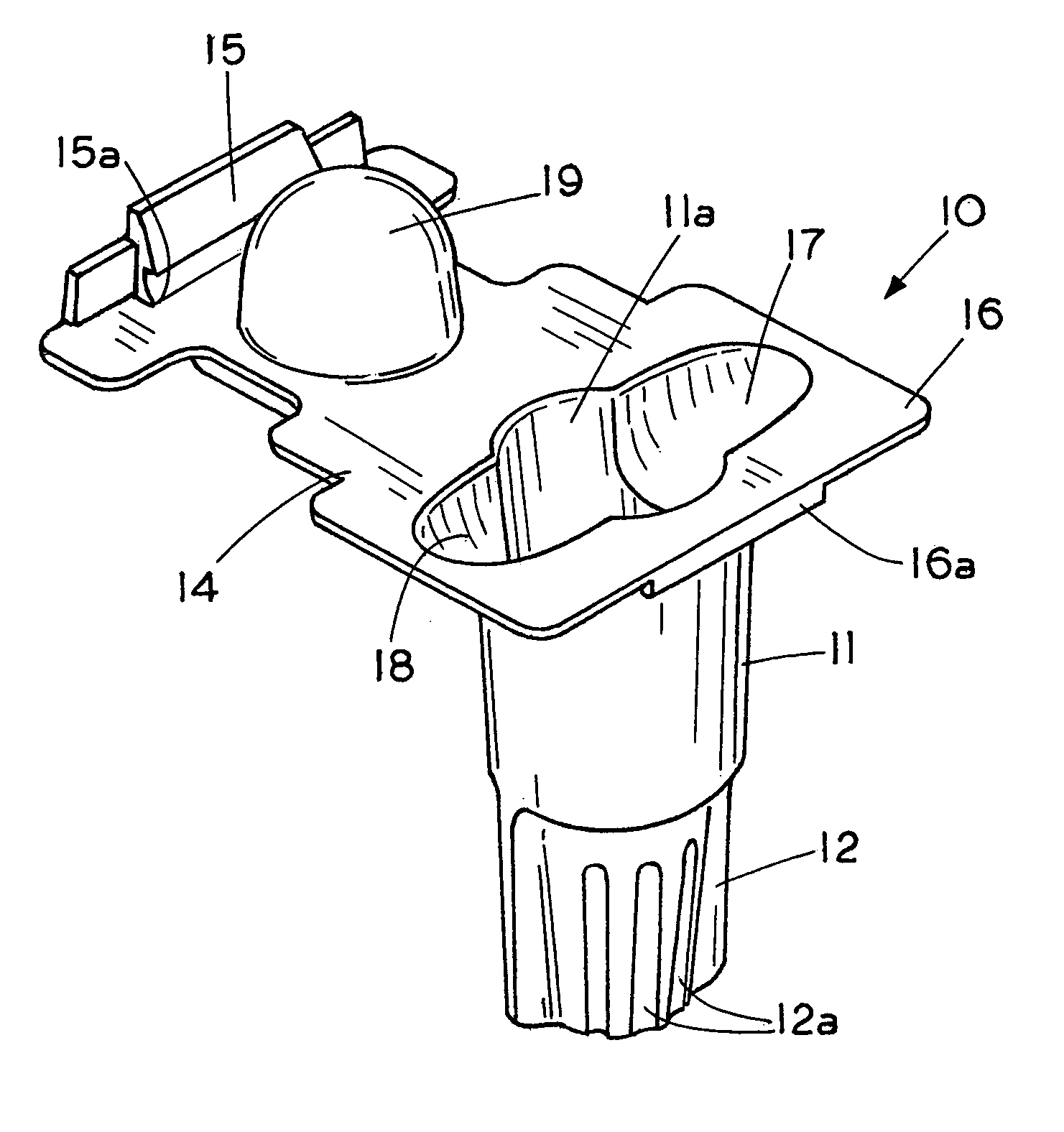
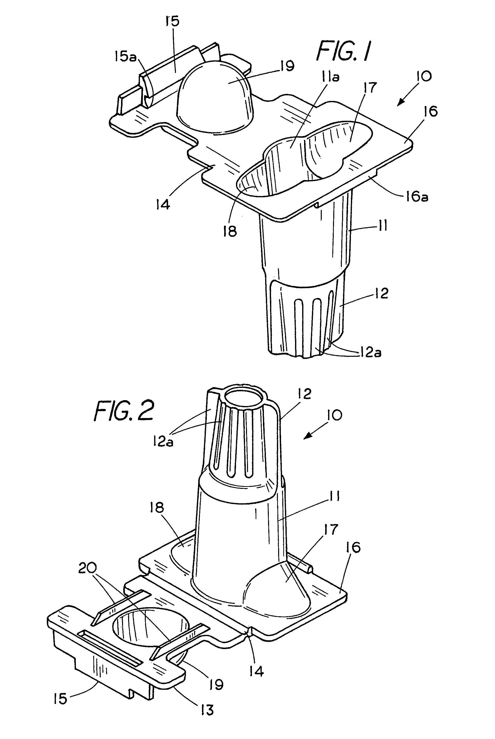
[0019]FIG. 1 shows a bottom perspective view of a one-piece direct bury connector 10 for use in underground locations where moisture can be expected and where one needs to inhibit strain on an electrical connection. FIG. 2 shows a top perspective view of the one-piece direct bury connector 10. Referring to FIG. 1 and to FIG. 2 the direct bury connector comprises a semi rigid elongated tube 11 made from a polymer plastic and having a twist-on wire connector forming a closed end 12 of tube 11. Tube 11 includes an open end 11a having a cover or cap 13 that can be brought into a closed condition on the open end 11a of tube 11 through a living hinge 14. That is, the exterior of twist-on wire connector 12 forms a grasping surface for the twist-on wire connector 12 with the grasping surface containing elongated ribs 12a. Extending laterally from the open end 11a of tube 11 are a first lateral wire passage 17 and a second lateral wire passage 18 that terminate in a lip 16 that extends radia...


PUM


Abstract

A direct bury twist-on wire connector for securing an electrical connection having a tube with an integral twist-on wire connector graspable from outside the tube while the inside of the tube and the inside of the twist-on wire connector carry a sealant therein and a cap secureable to an open end of the tube to inhibit strain on the wires to thereby provide a ready-to-bury connector.

Description

CROSS REFERENCE TO RELATED APPLICATIONS[0001]This application is a continuation-in-part of U.S. application Ser. No. 10 / 928,669 titled STRAIN RELIEVED WIRE CONNECTOR filed Aug. 26, 2004 (pending), which is a continuation in part of application No. 10 / 654,076 titled STRAIN RELIEVED WIRE CONNECTOR filed Sep. 3, 2003 which is now U.S. Pat. No. 6,815,616.FIELD OF THE INVENTION[0002]This invention relates generally to direct bury electrical connectors and, more specifically, to a direct bury twist-on wire connector providing strain relief that can be quickly brought into a ready-to-bury condition and, if necessary, allow an electrical connection in the direct bury twist-on wire connector to be reworked.STATEMENT REGARDING FEDERALLY SPONSORED RESEARCH OR DEVELOPMENT[0003]NoneREFERENCE TO A MICROFICHE APPENDIX[0004]NoneBACKGROUND OF THE INVENTION[0005]The concept of waterproof twist-on wire connectors wherein a sealant is placed in the cavity of a twist-on wire connector is known in the ar...

Claims


Application Information

Patent Timeline
IPC IPC(8): H01R4/00
CPCH01R4/22H01R13/5812H01R13/595H01R13/5833H01R13/59H01R13/5825
Inventor KING, JR., LLOYD HERBERTBELGERI, MICHAELKEEVEN, JAMES C.
Owner THE PATENT STORE
Why Eureka
Try Eureka