
Transmission response measurement system and method of using time gating

a technology of time gating and measurement system, which is applied in the direction of resistance/reactance/impedence, special purpose recording/indication apparatus, instruments, etc., can solve the problems of inability to readily or directly access one of the ends, inability to transmit response, and inability to connect to the measurement system

Active Publication Date: 2007-01-30
KEYSIGHT TECH
View PDF12 Cites 27 Cited by
  • Summary
  • Abstract
  • Description
  • Claims
  • Application Information

AI Technical Summary

Problems solved by technology

Unfortunately, in some situations one of the first port and the second port of the exemplary DUT may not be readily accessible for connection to the measurement system (e.g., VNA).
For example, when attempting to determine a transmission response of a DUT comprising a long cable installed in a cellular telephone tower or in a wing of an aircraft, one or more of a distance between a first end and a second end of the cable and an inability to readily or directly access one of the ends may preclude connecting a VNA simultaneously to both ends of the cable.
In such exemplary situations, a conventional forward S-parameter measurement of the DUT using a VNA to determine the transmission response may not be possible or, at the very least, is rendered inconvenient.

Method used


Image

  • Transmission response measurement system and method of using time gating
  • Transmission response measurement system and method of using time gating
  • Transmission response measurement system and method of using time gating

Examples


Embodiment Construction

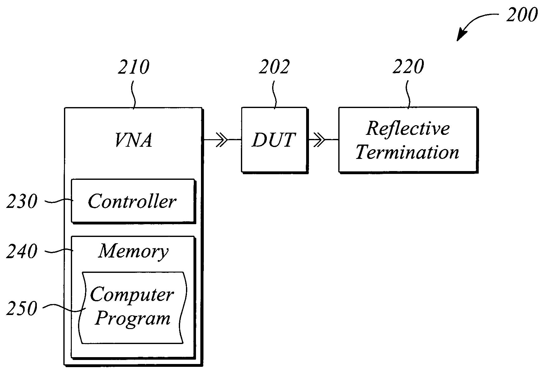
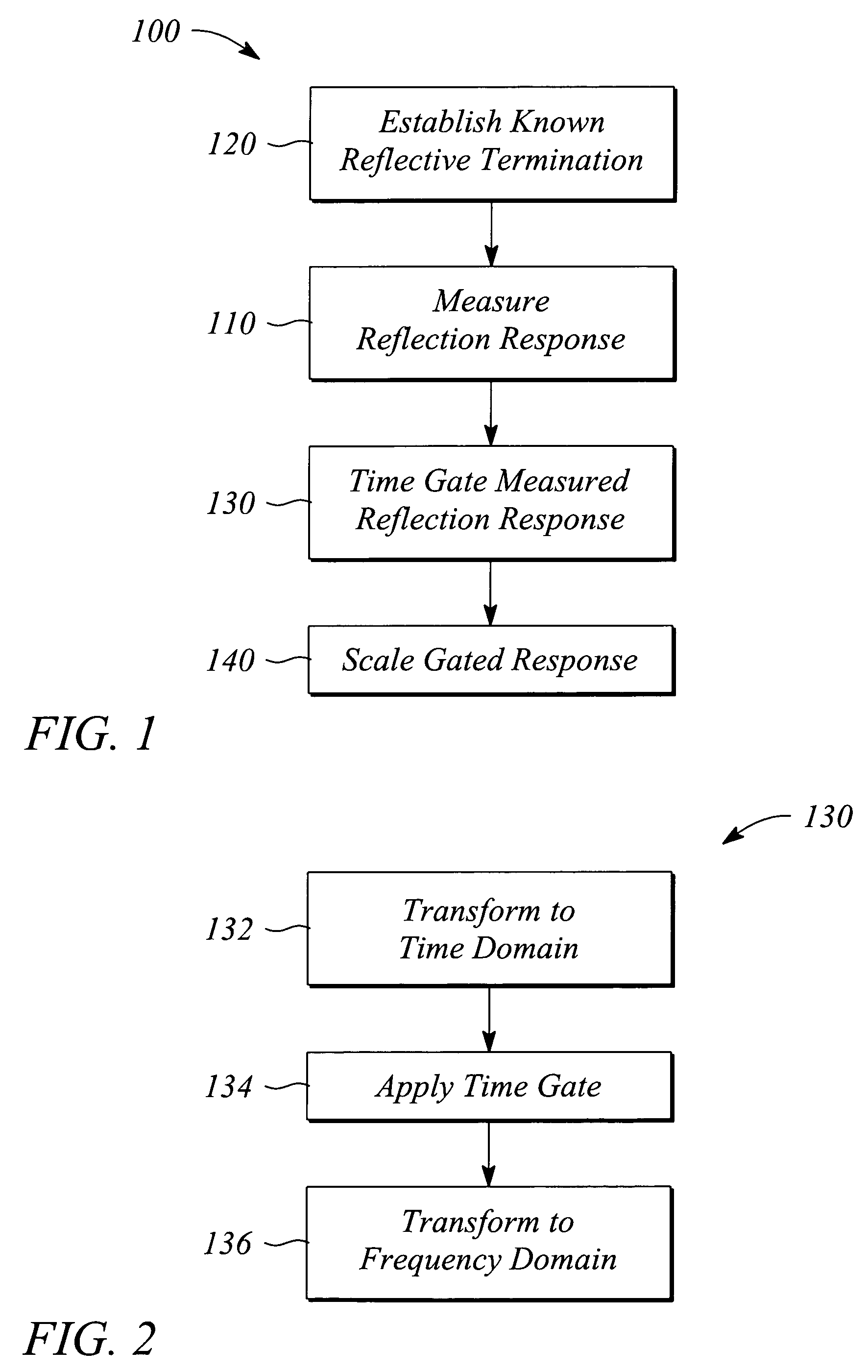
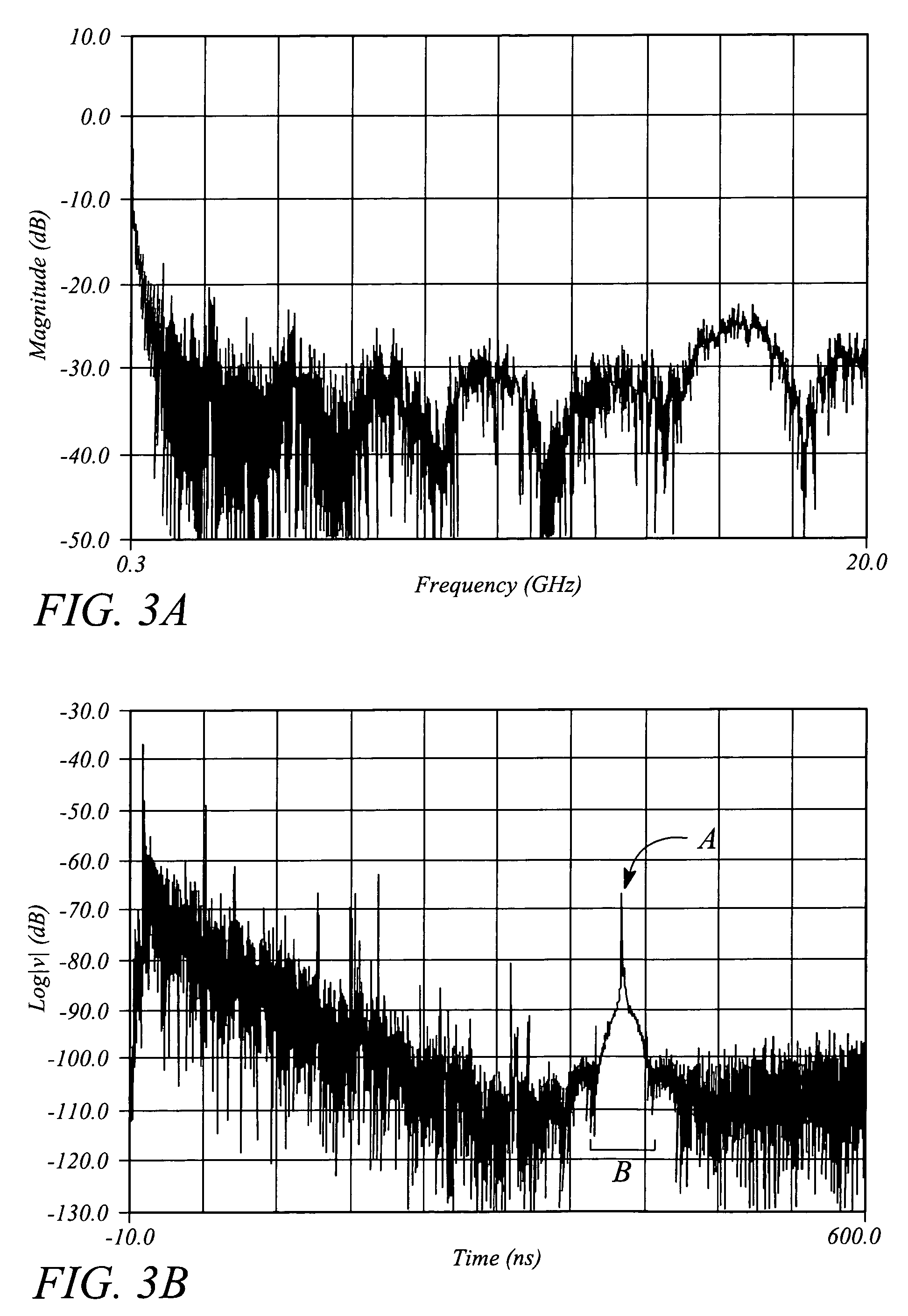
[0020]The embodiments of the present invention facilitate determining a transmission response of a device under test (DUT). In particular, according to the various embodiments of the present invention, the transmission response is determined using a measured reflection response in conjunction with time gating of the measured response. The reflection response measurement is performed at a first port (e.g., port-1) of the DUT. The time gating selects or isolates from the measured reflection response a response portion corresponding to a ‘known’ reflective termination at a second port (e.g., port-2) of the DUT. The reflection response portion isolated by the time gating also referred to herein as a ‘gated reflection response’ or simply ‘gated response’ essentially represents the transmission response of the DUT. Specifically, the gated reflection response is a determined two-way transmission response of the DUT. In some embodiments, a one-way transmission response of the DUT may be det...


PUM


Abstract

A method and a measurement system determine a transmission response of a device under test (DUT). The method includes measuring a reflection response from a first port of the DUT while a known reflective termination is on a second port of the DUT, and time gating the measured reflection response to produce a gated reflection response that is the transmission response of the DUT. The measurement system includes a vector network analyzer, a controller, a memory and a computer program. The computer program includes instructions that implement measuring the reflection response from the first port of the DUT, and further implement time gating the measured reflection response. The time gating isolates reflection data associated with the known reflective termination from the measured reflection response.

Description

CROSS-REFERENCE TO RELATED APPLICATIONS[0001]N / ASTATEMENT REGARDING FEDERALLY SPONSORED RESEARCH OR DEVELOPMENT[0002]N / ABACKGROUND[0003]A transfer function or transmission response represented as a function of frequency characterizes a performance of a radio frequency (RF) device under test (DUT) in a frequency domain. The transmission response, sometimes also termed a ‘complex transmission response’, is generally specified either in terms a real response and an imaginary response (i.e., as a complex number) or equivalently in terms of a magnitude response and a phase response of the DUT as a function of frequency across a band or range of frequencies of interest. For example, the transmission response of a DUT may comprise a magnitude response and a phase response of the DUT measured or otherwise determined at a plurality of frequencies spanning an operational frequency range of the DUT. The transmission response essentially characterizes an effect that the DUT has on signals passi...

Claims


Application Information

Patent Timeline
Patent Type & Authority Patents(United States)
IPC IPC(8): G01R31/11G01R27/28G01R35/00
CPCG01R27/28
Inventor DUNSMORE, JOEL P.
Owner KEYSIGHT TECH
Learn More