Active matrix liquid crystal image generator

a liquid crystal image and active matrix technology, applied in the field of miniature display systems, can solve the problems of difficult miniaturization of conventional display technologies such as crts, lack of promising in this field, and each prior art device has significant limitations in resolution, brightness, compactness, lumination efficiency, or color capability

Inactive Publication Date: 2007-01-30
CITIZEN FINETECH MIYOTA CO LTD
View PDF55 Cites 3 Cited by
  • Summary
  • Abstract
  • Description
  • Claims
  • Application Information

AI Technical Summary

Benefits of technology

[0009]In accordance with one data ordering scheme, the gray scale of any given pixel is obtained by dividing each frame into subframes of time periods, preferably time periods of unequal length, while maintaining the light directed into the modulator at a fixed brightness and by either turning ON or OFF the particular pixel during certain subframes of the frame such that the cumulative time in which the pixel is ON during the frame is proportional to the desired gray scale for that pixel. Alternatively, in accordance with a second data ordering scheme, the gray scale of any given pixel is obtained by dividing each frame into subframes of equal time periods and by turning ON or OFF the particular pixel during certain subframes of the frame while at the same time changing the brightness of light directed into the spatial light modulator for the different subframes. The cumulative time in which the pixel is ON, in combination with the brightness of the light during each subframe, is proportional to the desired gray scale for that pixel. A third scheme is a combination of the first scheme and the second scheme. In each of these schemes, because of the frame rate, the viewer's eye perceives the time integral of brightness of each pixel for each frame, thereby perceiving the desired gray scale image. In both of these second and third data ordering schemes, additional blackout subframes are provided in accordance with the present invention in order to maintain the fidelity of the ultimately produced display.

Problems solved by technology

One of the ongoing challenges facing the manufacture of miniature display systems is providing smaller and smaller displays with higher and higher resolution.
Conventional display technologies such as CRTs are difficult to miniaturize and therefore do not hold much promise in this field.
However, each of these prior art devices has significant limitations in resolution, brightness, compactness, lumination efficiency, or color capability.

Method used


Image

  • Active matrix liquid crystal image generator
  • Active matrix liquid crystal image generator
  • Active matrix liquid crystal image generator

Examples


Embodiment Construction

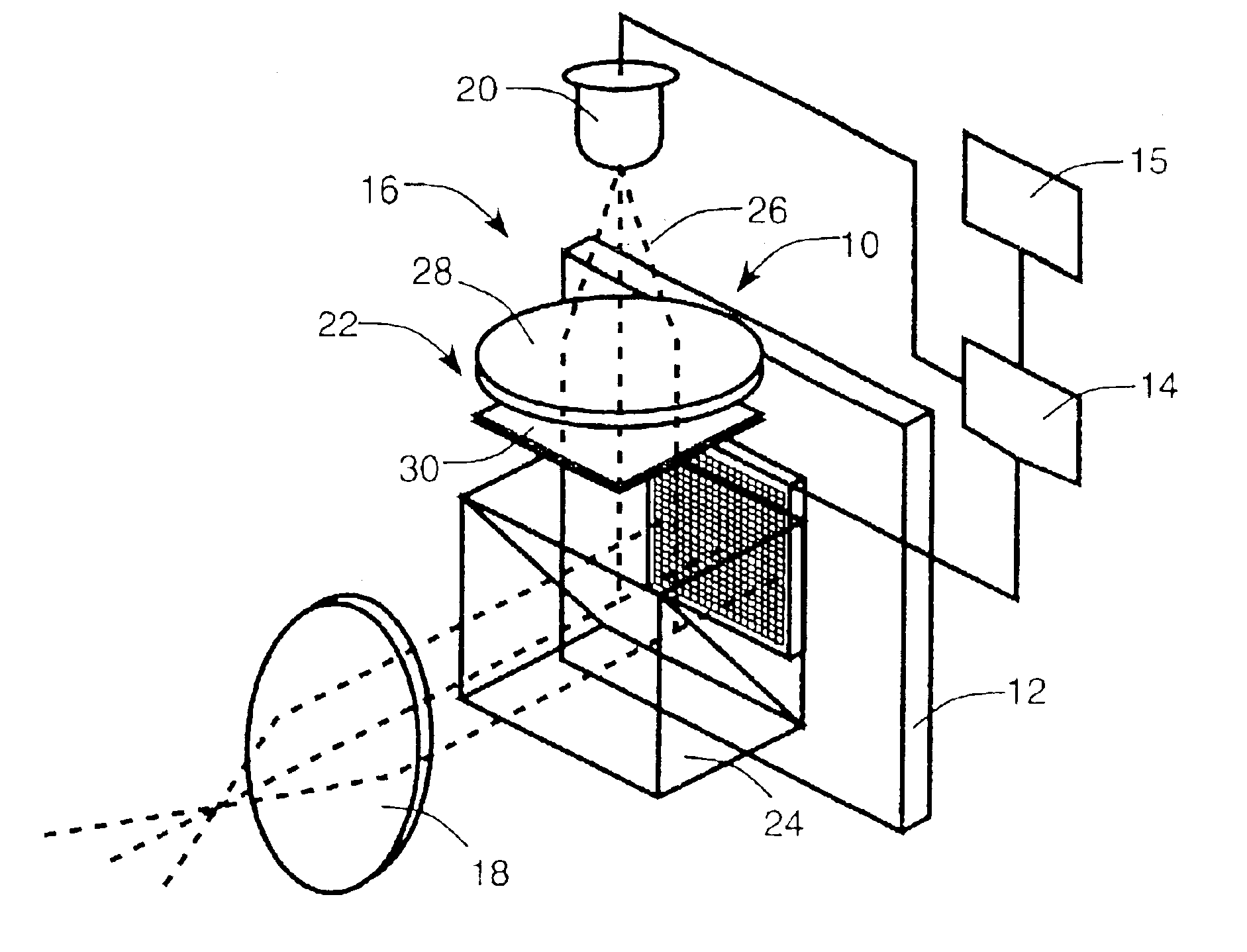
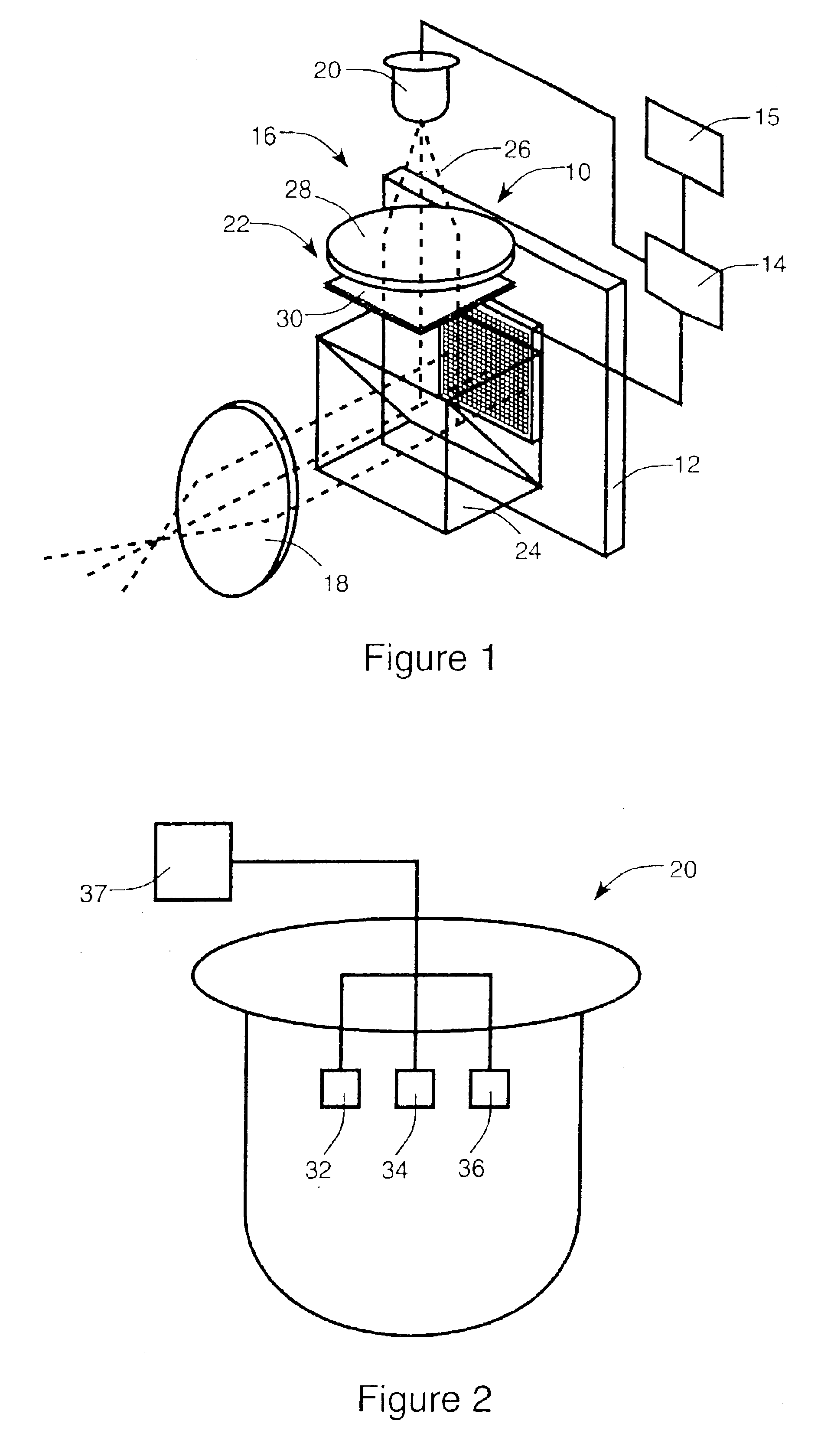
[0031]Referring initially to FIG. 1, a preferred embodiment of a miniature display system designed in accordance with the present invention and generally designated by reference numeral 10 is illustrated. As will be described in more detail hereinafter, the display system includes a ferroelectric liquid crystal VLSI (FLC / VLSI) spatial light modulator 12; a data writing arrangement 14 for controlling FLC / VLSI spatial light modulator 12; a video or digitized image source 15 which creates or provides, as an input to data writing arrangement 14, digitized images; an illumination arrangement generally designated by reference numeral 16 for illuminating spatial light modulator 12; and an appropriately designed readily available viewing eyepiece lens 18. As will also be described in more detail hereinafter, FLC / VLSI spatial light modulator 12 includes an array of individually addressable pixels, not shown in FIG. 1, designed to be switched by data writing arrangement 14 between ON (light) ...


PUM


Abstract

A system for producing spatially modulated monochrome or color light having gray scale includes an active matrix liquid crystal spatial light modulator having light modulating means including (i) a layer of ferroelectric liquid crystal material which is designed to switch between ON and OFF states and (ii) active matrix means including VLSI circuitry for dividing the layer of liquid crystal material into an array of individual liquid crystal pixels and for causing each of the pixels of liquid crystal material to modulate light individually by switching between the ON and OFF states in a way that depends upon the data which the VLSI circuitry is written. The system also includes illumination means having a light source for directing light from the source into the pixel-divided layer of ferroelectric liquid crystal material in a specific way. And finally, the system includes means for writing the VLSI circuitry with preselected data in accordance with a particular data ordering scheme such that the circuitry, in response to the written data, causes the pixels of liquid crystal material to individually switch between their ON and OFF states and therefore modulate light from the source in a way which, depending upon the data, produces a specific overall pattern of gray scale light.

Description

RELATED APPLICATIONS[0001]This application is a continuation of U.S. patent application Ser. No. 09 / 045,247, filed on Mar. 20, 1998, now U.S. Pat. No. 6,570,550, which is a continuation of U.S. patent application Ser. No. 08 / 362,665, filed on Dec. 22, 1994, now issued as U.S. Pat. No. 5,748,164, the contents of which are incorporated herein by reference.GOVERNMENT CONTRACT CLAUSE[0002]This invention was made with Government support under contracts NAS9-18858 and NAS9-19102 awarded by the National Aeronautics and Space Administration and contracts DAA-H01-92-C-R275 and DAA-H01-94-C-R154 awarded by the Advanced Research Projects Agency. The Government has certain rights to this invention.BACKGROUND OF THE INVENTION[0003]The present invention relates generally to display systems, and more particularly to a miniature display system in which a ferroelectric liquid crystal (FLC) spatial light modulator is positioned directly on top of and controlled by a specifically written (i.e. address...

Claims


Application Information

Patent Timeline
Patent Type & Authority Patents(United States)
IPC IPC(8): G09G3/36G09G3/20G09G3/34
CPCG09G3/3406G09G3/3651G02F1/133553G09G2320/064G02F1/136277G02F1/141G02F2001/133622G02F2203/12G02F2203/30G09G3/2022G09G3/2025G09G3/2029G09G3/2081G09G2310/0235G09G2310/0237G09G2310/0278G09G2310/061G09G2320/0633G02F1/135G02F1/133622
Inventor HANDSCHY, MARK A.MEADOWS, MICHAEL R.
Owner CITIZEN FINETECH MIYOTA CO LTD
Why Eureka
Try Eureka