CT scanner system and method for improved positioning

a scanner and positioning technology, applied in the direction of instruments, radiation beam directing means, applications, etc., can solve the problem of difficult to determine the correct position of the patien

Active Publication Date: 2007-01-30
XORAN TECH
View PDF7 Cites 28 Cited by
  • Summary
  • Abstract
  • Description
  • Claims
  • Application Information

AI Technical Summary

Problems solved by technology

Because the x-ray source is a fan-beam x-ray source, imaging only a narrow slice at a time, it is difficult to determine the correct position of the patient.
In addition, the CT scanner exposes the doctor and the patient to radiation.
Although the doctor can avoid excessive doses of radiation by remotely controlling the system, the continuous scanning by the CT scanner exposes the patient's body to more radiation than necessary.

Method used


Image

  • CT scanner system and method for improved positioning
  • CT scanner system and method for improved positioning
  • CT scanner system and method for improved positioning

Examples


Embodiment Construction

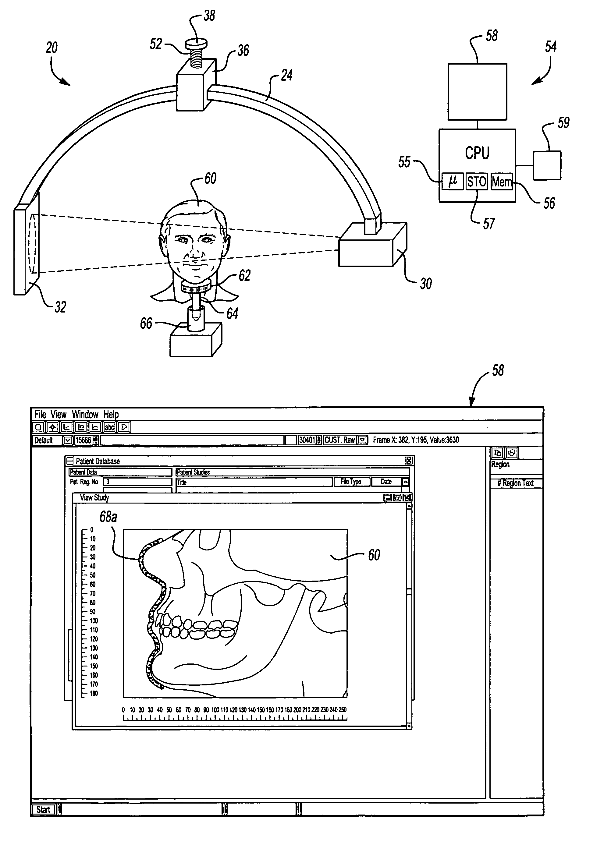
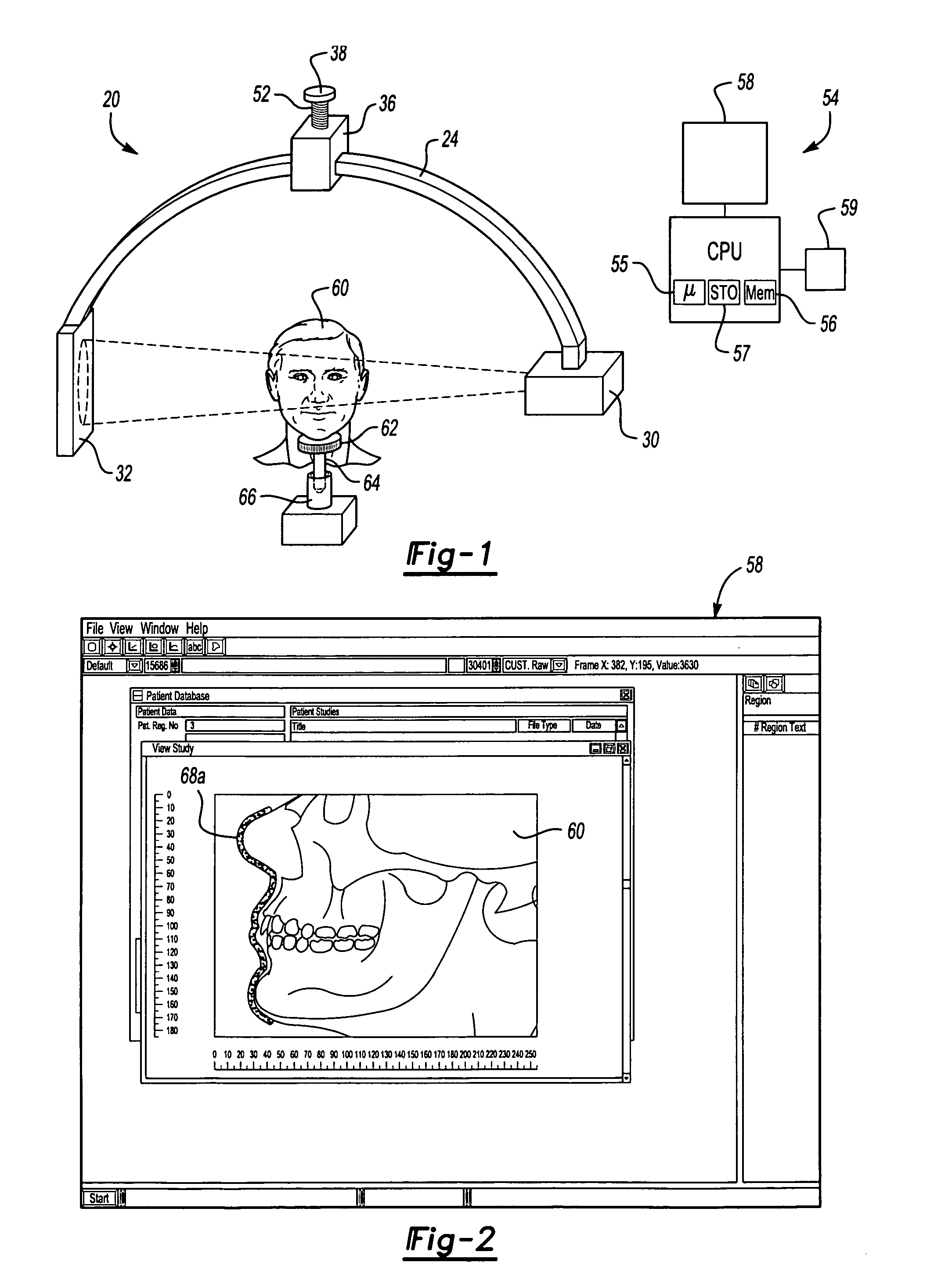
[0014]A CT scanner 20 according to the present invention is illustrated in FIG. 1. The CT scanner 20 includes a c-arm 24 connected at one end to an x-ray source 30, which in this embodiment is a cone-beam x-ray source 30. The other end of the c-arm 24 supports a complementary detector 32. The detector 32 is a two-dimensional detector as shown. The center of the c-arm is supported by a motor 36 for rotating the c-arm 24 relative to a mounting plate 38. The CT scanner 20 may optionally include a ball screw 42 connecting the motor 36 to the mounting plate 38, such that during the single revolution, the CT scanner 20 also translates approximately 1 inch along the axis of rotation, thus providing additional data for the computer 54

[0015]The CT scanner 22 further includes a computer 54 including a microprocessor or CPU 55, memory 56, a hard drive 57 and / or other optical, magnetic, electronic or other mass storage, and other hardware and software for performing the functions described here...


PUM

PropertyMeasurementUnit
CTaaaaaaaaaa
CT scanaaaaaaaaaa
Computed tomographyaaaaaaaaaa

Abstract

The CT scanning system of the present invention includes a source and detector mounted to a c-arm. The c-arm is positioned on a mounting plate and ball screw to rotate about an axis centered within the c-arm and to also translates along the axis of rotation. A computer controls the rotation of the CT scanner, the x-ray source, and collects the data from the detector to create an image. The CT scanner first takes a scout scan prior to the full acquisition of the data. The scout scan is a single two-dimension image. The CPU draws locating marks on the scout scan image to indicate the desired location. When proper alignment is verified, the processor then controls the motor to perform one complete revolution of the c-arm, during which time the computer collects multiple images from the detector.

Description

[0001]This application claims priority to U.S. Provisional Patent Application Ser. No. 60 / 513,409, filed Oct. 22, 2003.BACKGROUND OF THE INVENTION[0002]Computed tomography (CT) scanners are used to provide information regarding internal organs of a patient. For example, CT scanners are often used to gather information regarding sinus cavities within a patient's head.[0003]The CT scanner includes an x-ray source and an x-ray detector on opposite sides of the patient's body near the area to be scanned. Current CT systems require the patient to be positioned relative to the x-ray source in order to obtain a clear image. The x-ray from the x-ray source is collimated to emit a fan-beam x-ray producing a plurality of “slices” through the patient's body as the x-ray source and detector revolve around the patient's body.[0004]Because the x-ray source is a fan-beam x-ray source, imaging only a narrow slice at a time, it is difficult to determine the correct position of the patient. When the ...

Claims


Application Information

Patent Timeline
Patent Type & Authority Patents(United States)
IPC IPC(8): G01N23/00A61B6/00
CPCA61B6/4441A61B6/488A61B6/501
Inventor SUKOVIC, PREDRAG
Owner XORAN TECH
Why Eureka
Try Eureka