Weapon sight having analog on-target indicators

a technology of on-target indicators and weapons, applied in the field of weapons aiming, can solve the problems of requiring a greater effort of a soldier, affecting the orientation of weapons, and affecting the accuracy of weapons, so as to facilitate weapon orientation

Active Publication Date: 2007-02-06
RAYTHEON CO
View PDF52 Cites 117 Cited by
  • Summary
  • Abstract
  • Description
  • Claims
  • Application Information

AI Technical Summary

Benefits of technology

[0008]One form of the invention relates to a weapon-mountable device having a range portion that specifies a range to a target, a sensor portion that provides sensor information representing an orientation of the device, an electronic control portion, and a sight that facilitates weapon orientation in preparation to fire a munition, and this form of the invention involves: causing the electronic control portion to be responsive to sensor information from the sensor portion and a range from the range portion for calculating how to hit the target with a munition; and causing an analog indicator that is part of the sight and disposed within the field of view of the sight to be responsive to the electronic control portion for indicating how to orient the weapon so the munition will hit the target.

Problems solved by technology

Although existing weapon sights have been generally adequate for their intended purposes, they have not been satisfactory in all respects.
Moreover, the sight for the grenade launcher is often mounted near the outer end of the rifle barrel, thereby adding weight at a location spaced from the center-of-mass of the overall weapon, and thus necessitating greater effort by a soldier to swing the weapon to bear and then hold it on a target.
Other existing laser rangefinders use a single aperture, but in association with a beam splitter having a transmissivity of approximately 50% for the laser wavelengths involved, resulting in approximately a 50% loss for the energy of the transmitted pulse, and another 50% loss for the reflected energy.
This is undesirable, because it reduces the maximum range that can be measured by the rangefinder.
Moreover, this is highly inefficient, which makes it undesirable for a battery-operated weapon sight, where any waste of energy reduces the amount of time that the weapon sight can operate before the battery becomes discharged.

Method used


Image

  • Weapon sight having analog on-target indicators
  • Weapon sight having analog on-target indicators
  • Weapon sight having analog on-target indicators

Examples


Embodiment Construction

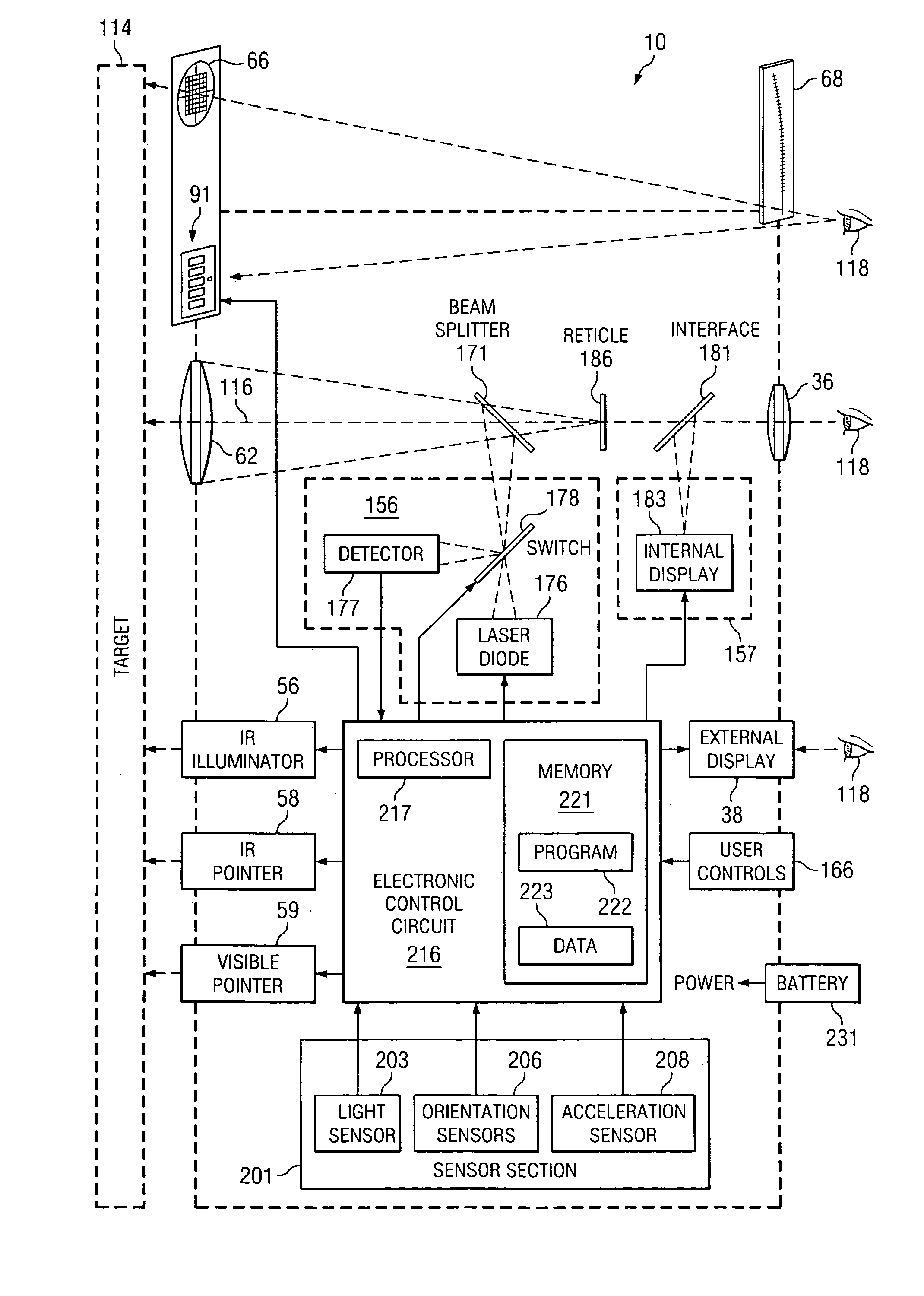
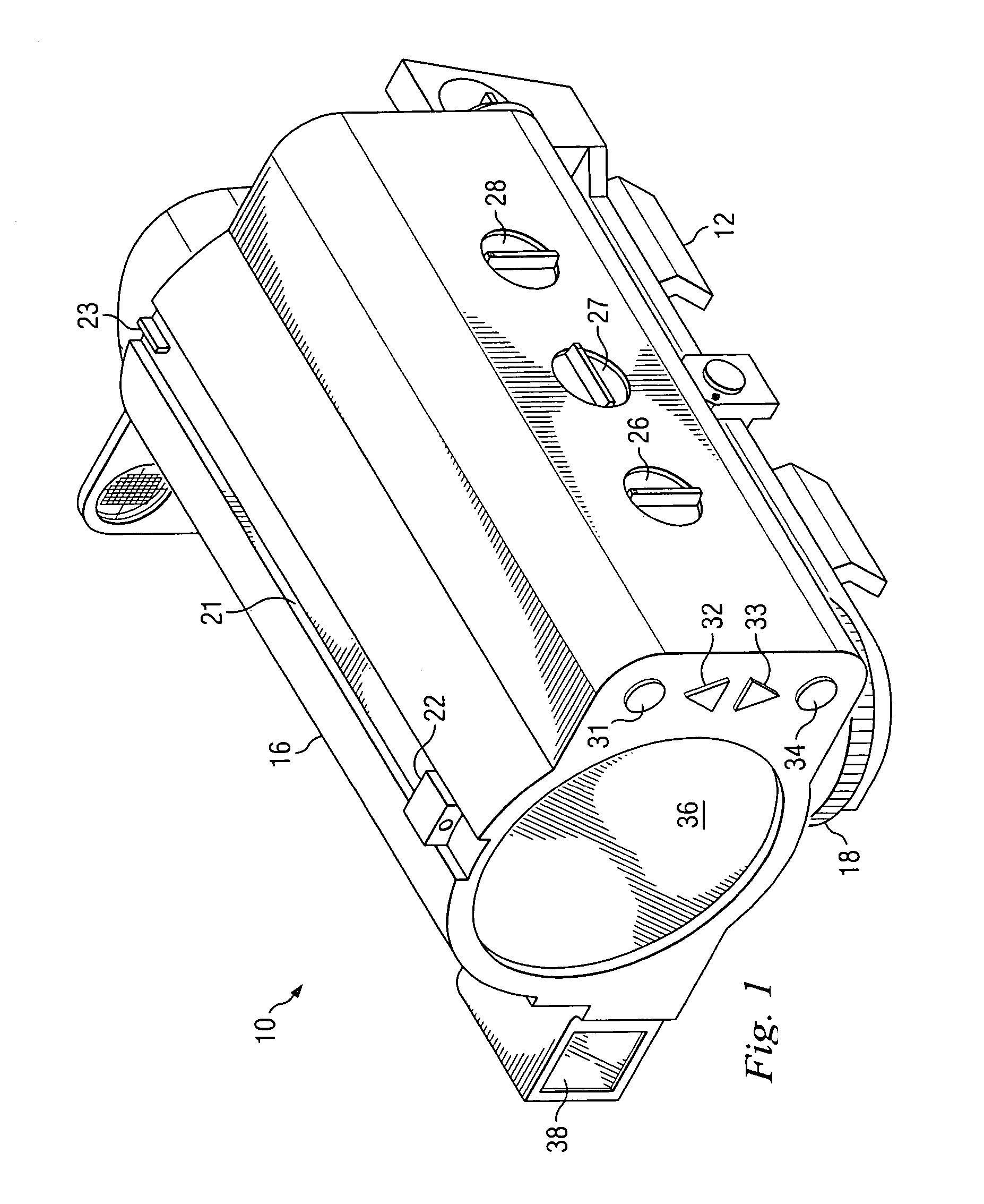
[0024]FIG. 1 is a diagrammatic perspective rear view of an apparatus that is a weapon sight 10, and that embodies aspects of the present invention. Although the disclosed weapon sight 10 happens to be a rifle sight, the present invention has aspects that are not limited to rifle sights, but can be used in sights for various different types of weapons. As discussed in more detail later, the weapon sight 10 is capable of use with a rifle that can fire at least two different types of munitions. One specific example would be a military rifle having a grenade launcher removably mounted on the barrel, such that a soldier can use the rifle to fire either a munition with a low arc trajectory (such as a bullet), or a munition with a high arc trajectory (such as a grenade).

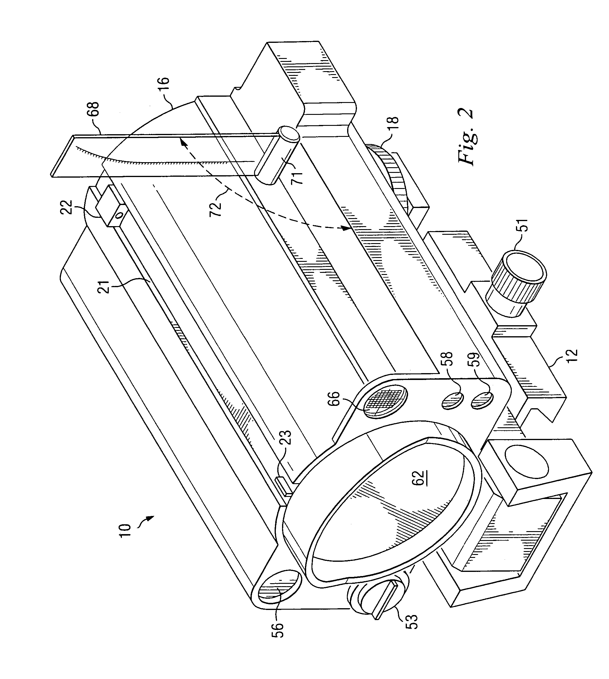
[0025]The sight 10 includes a rail mount 12 that can fixedly but removably mount the sight 10 on the receiver or mounting rail of a firearm. The sight 10 includes a housing 16. The position of the housing 16 can be adjusted...


PUM


Abstract

A device has structure that can support the device on a weapon, and a range portion that specifies a range to a target. A sensor portion provides sensor information representing an orientation of the device, and an electronic control portion is responsive to sensor information from the sensor portion and a range from the range portion for calculating how to hit the target with a munition. The device includes a sight that facilitates weapon orientation in preparation to fire the munition, the sight having an analog indicator that is disposed within its field of view and that is responsive to the electronic control portion for indicating how to orient the weapon so that the munition will hit the target.

Description

[0001]This application claims the priority under 35 U.S.C. §119 of provisional application No. 60 / 552,262 filed Mar. 10, 2004.TECHNICAL FIELD OF THE INVENTION[0002]This invention relates in general to techniques for aiming weapons and, more particularly, to a weapon sight that can be mounted on a weapon in order to assist with accurate aiming of the weapon.BACKGROUND OF THE INVENTION[0003]Over the years, various techniques and devices have been developed to help a person accurately aim a weapon such as a rifle. One common approach is to mount a sight or scope on the weapon. A person then uses the sight or scope to view an intended target in association with a reticle, often with a degree of magnification. Although existing weapon sights have been generally adequate for their intended purposes, they have not been satisfactory in all respects.[0004]For example, it is very common for a solder to carry both a rifle and a grenade launcher. The grenade launcher is detachably coupled to th...

Claims


Application Information

Patent Timeline
Patent Type & Authority Patents(United States)
IPC IPC(8): F41G1/48
CPCF41G1/48F41G1/35
Inventor STALEY, III, JOHN R.
Owner RAYTHEON CO
Why Eureka
Try Eureka