
Delivery catheter

a catheter and catheter tube technology, applied in the field of catheterization, can solve the problems of support frame and so easily distorted, and achieve the effect of easy distorted

Inactive Publication Date: 2007-02-06
SALVIAC
View PDF10 Cites 110 Cited by
  • Summary
  • Abstract
  • Description
  • Claims
  • Application Information

AI Technical Summary

Benefits of technology

[0012]By using a tubular loading means which is movable relative to the medical device for its securement, it is possible to grip the medical device in whatever way one requires and thus ensure that, for example, with a compressible or distortable medical device it is not compressed in an undesired way. Further, as the loading device is tubular, it provides continuous support fully around the medical device ensuring an even compression of the medical device. This is particularly desirable with foam type medical devices which do not have a support frame and so are easily distorted. The tubular loading means allows controlled compression of such medical devices so that they will open in a desired manner upon deployment.

Problems solved by technology

This is particularly desirable with foam type medical devices which do not have a support frame and so are easily distorted.

Method used


Image

  • Delivery catheter
  • Delivery catheter
  • Delivery catheter

Examples


Embodiment Construction

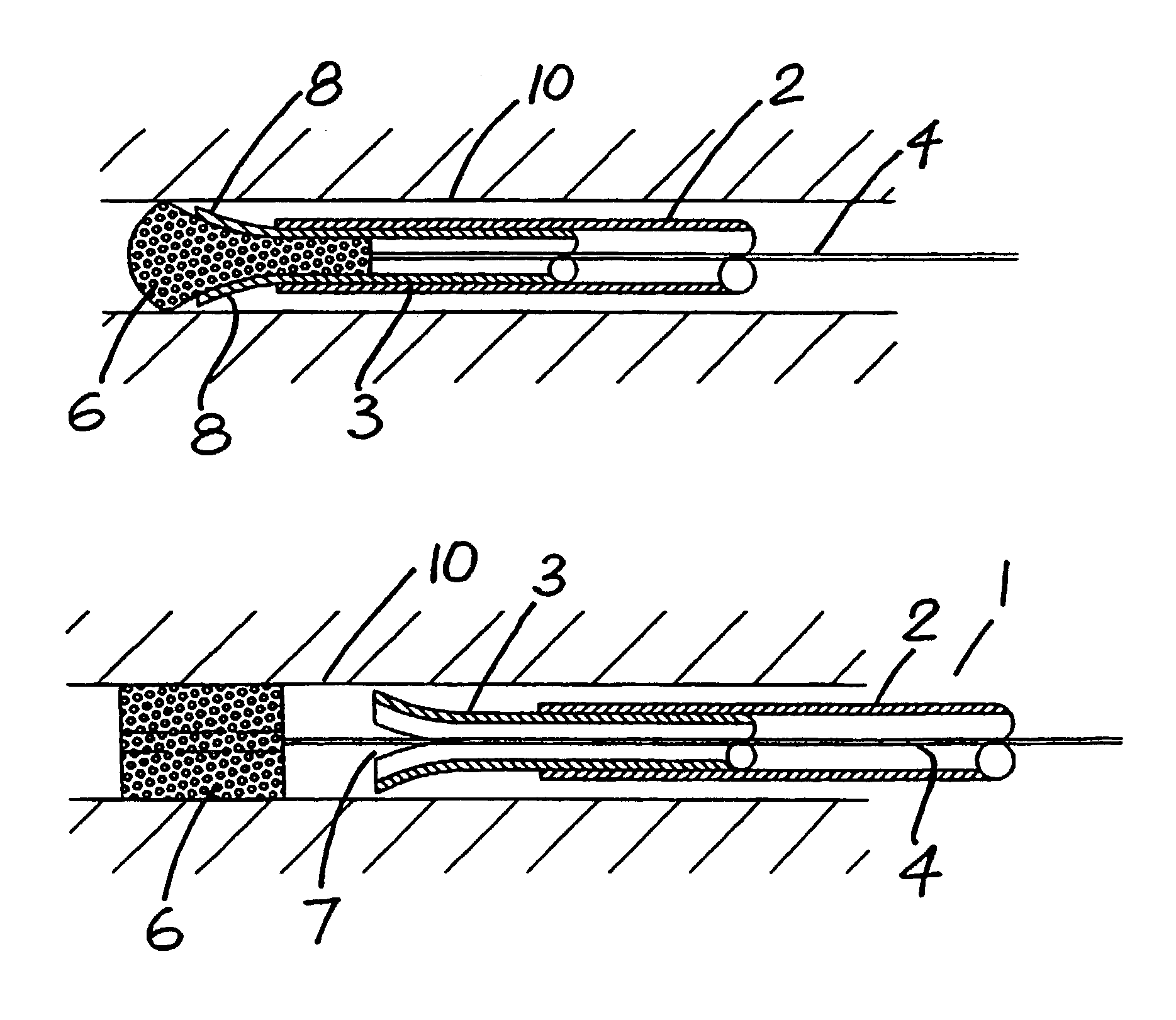
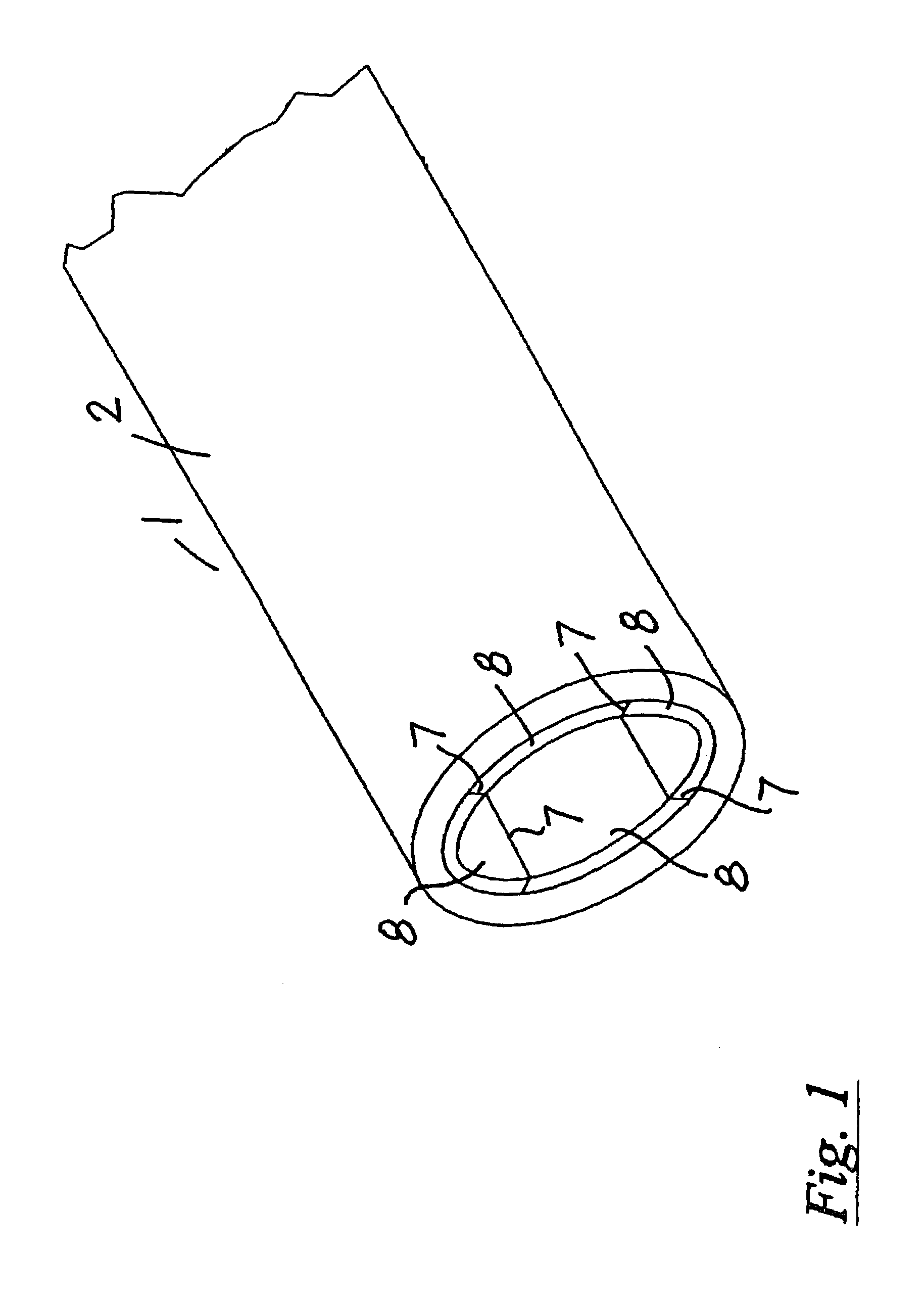
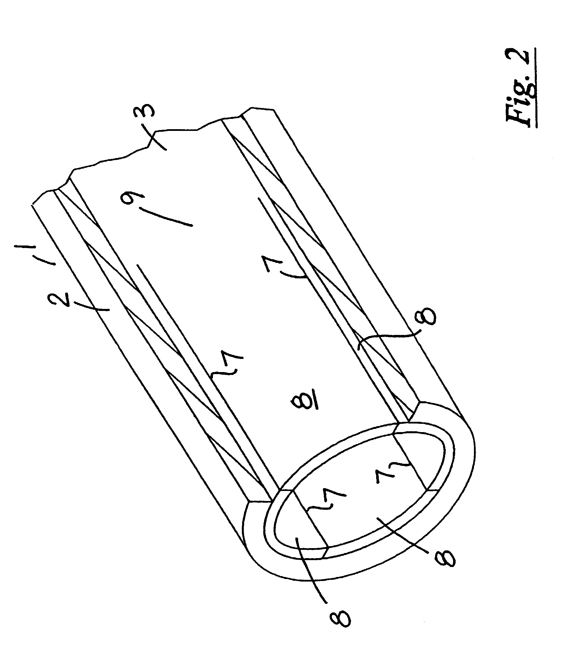
[0036]Referring to the drawings, and initially to FIGS. 1 to 5 thereof, there is illustrated a catheter according to the invention indicated generally by the reference numeral 1 and comprising an outer catheter tube 2 within which is slidably mounted an inner tubular sheath 3 which in turn houses a guide wire 4 which is slidable within the inner tubular sheath 3. At an outer end of the guide wire 4 is a gripper 5 of any suitable construction engaging a medical implant device 6 of compressible foam or other porous material. An outer end of the inner tubular sheath 3 is provided with four circumferentially spaced apart and axially arranged slits 7 which sub-divide the tubular side wall at the outer distal end of the inner tubular sheath 3 into four tube sections 8.

[0037]Each of the tube sections 8 is attached by a hinge joint 9 at an inner end of the tube section 8 to the inner support tube 3. Thus, each tube section 8 will pivot about the hinge joint 9 for movement between a closed p...


PUM


Abstract

A catheter (1) for transvascular deployment of a radially compressible medical device (16) has a tubular outer body (2) within which is slidably mounted an inner tubular sheath (3) which in turn houses a guide wire (4) which is axially movable through the sheath (3). The medical device (6) is mounted on the guide wire (4) and can be collapsed within the sheath (3) and body (2) for deployment. An outer distal end of the sheath (3) is provided with circumferentially spaced-apart axial slits (7) extending proximally from the distal end of the sheath (3) which sub-divide the distal end of the tubular side wall of the sheath (3) into a number of complementary tube sections (8) which are movable apart when the sheath (3) is pushed out of the distal end of the body (2) to engage or deploy the medical device (6).

Description

[0001]This application is a continuation of U.S. application Ser. No. 09 / 676,085, filed Oct. 2, 2000, now U.S. Pat. No. 6,514,280, which is a continuation of International Application No. PCT / IE99 / 00020, filed Apr. 1, 1999.FIELD OF THE INVENTIONBACKGROUND OF THE INVENTION[0002]There are many forms of medical implant devices, deployed transvascularly by means of a catheter, which are used where there is a requirement to occlude a vessel, fill a void or plug a defect in the treatment of medical conditions, whether they be acute or chronic situations or cosmetic situations.[0003]These medical implant devices are delivered either transarterially or transvenously. The medical implant device is loaded in a folded or collapsed position within a tip of a catheter. The tip of the catheter is directed to the defect which is to be repaired and then the medical implant device is delivered from the catheter. Once out of the catheter the medical implant device is expanded to its full size to occl...

Claims


Application Information

Patent Timeline
IPC IPC(8): A61F2/06A61F11/00A61F2/95A61F2/966A61F2/97
CPCA61B17/12031A61B17/12109A61B17/12181A61F2/95A61F2/966A61F2/97A61B2017/1205A61F2002/9534A61F2002/9522A61B2017/12095A61F2/9522
Inventor GILSON, PAUL
Owner SALVIAC
Learn More