Fluid cooled electrical assembly

a technology of electrical assembly and flue gas, which is applied in the direction of indirect heat exchangers, laminated elements, lighting and heating apparatus, etc., can solve the problems of diamond, difficult design of heat sinks for power circuits, and need to dissipate heat created

Active Publication Date: 2007-02-06
RINEHART MOTION SYST
View PDF24 Cites 89 Cited by
  • Summary
  • Abstract
  • Description
  • Claims
  • Application Information

AI Technical Summary

Benefits of technology

[0008]In a second separate aspect, the present invention is a method of cooling a heat producing assembly that uses a housing made of liquid-impermeable, dielectric material, which has an opening. An electrical package, which supports a set of semiconductor electrical devices on a first major surface and has a second major surface that forms a heat sink adapted to express heat generated from the electrical package, has its heat sink surface fit into the opening. Fluid that is cool relative to the second major surface is caused to pass by the opening, thereby cooling the second major surface.

Problems solved by technology

One critical problem encountered in the design of power circuitry (and other heat producing circuitry) is the need to dissipate heat created.
Unfortunately, a number of difficult problems arise in the design of a heat sink for power circuitry.
One exception, diamond, is expensive and very hard, making it difficult to form into a desired shape.
Although diamond dust can be used, typically mixed with aluminum, this also proves expensive and difficult to cast.
Another challenge is the need to maintain electrical isolation between the electrical devices and heat sinking structure.
Expressing the heat from the free side of the DBC can be a problem because of the large amount of heat being conducted to the free side.
One problem that occurs in the production of electric assemblies is that of rigidly connecting to a housing a rigid conductive member that has been flow soldered to a component.
These operations, however, tend to torque the rigid conductive member, as it is being secured, and this places a shear forces onto the solder bond, weakening it.

Method used


Image

  • Fluid cooled electrical assembly
  • Fluid cooled electrical assembly
  • Fluid cooled electrical assembly

Examples


Embodiment Construction

)

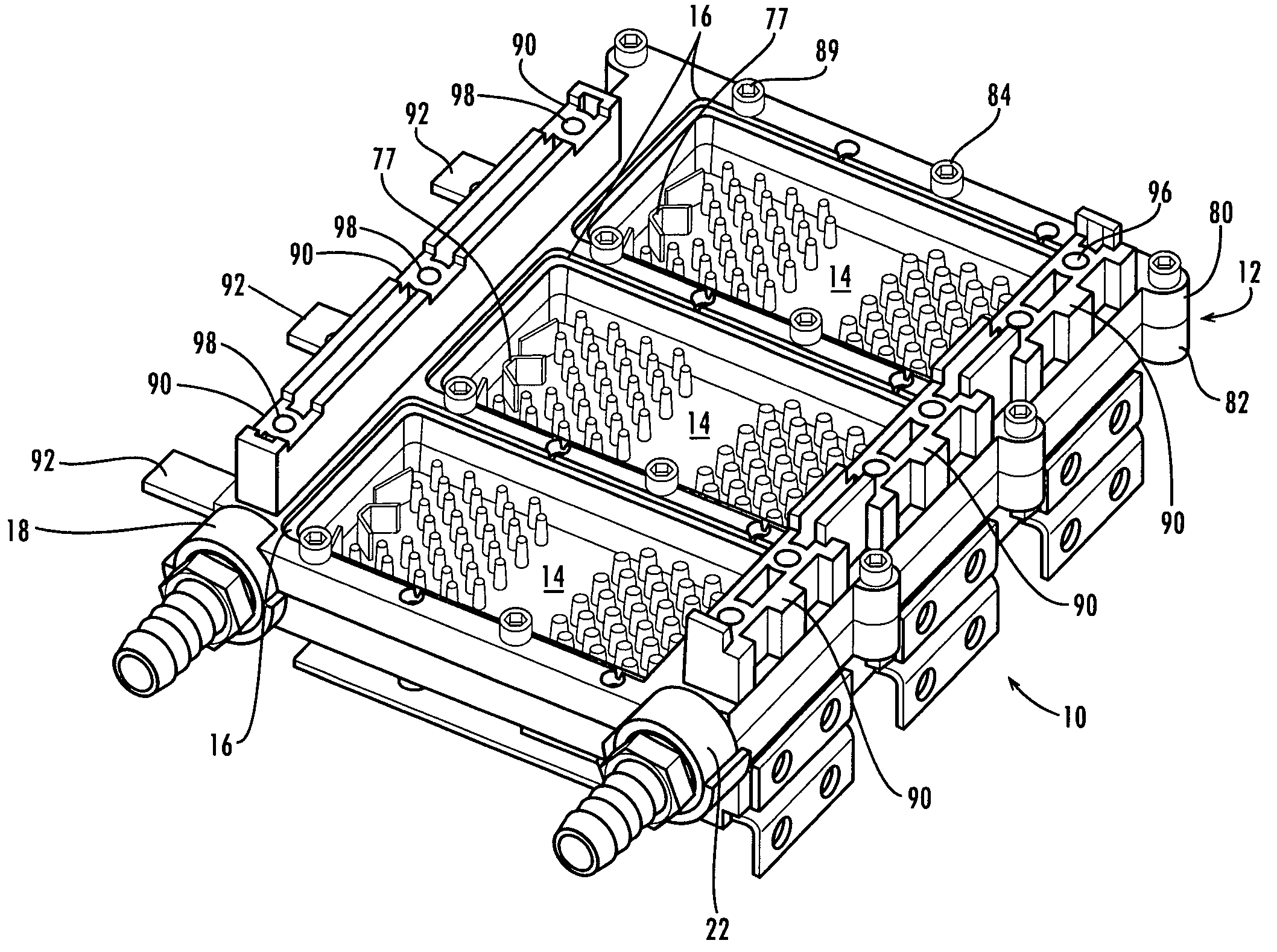
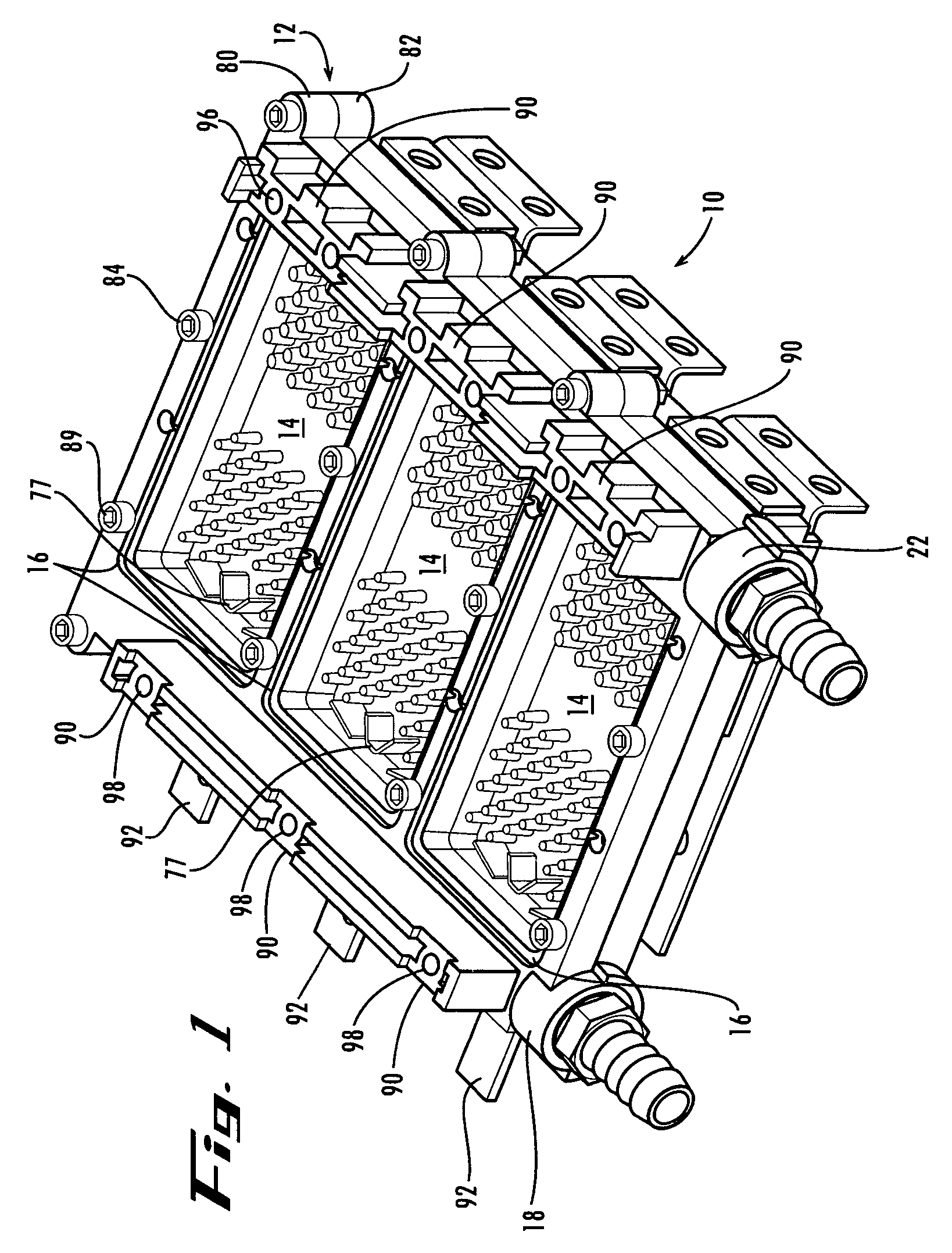
[0017]Referring to FIG. 1 a preferred embodiment of a power assembly according to the present invention is a power assembly 10 made of a housing 12 that is adapted to accept and retain a set of six power circuit packages 14. Three packages 14 fit into a set of openings 16 on the bottom side of housing 12, and three additional packages 14 fit into additional openings 16 on the top side of housing 12. Housing 12 also accepts liquid coolant through fluid inlet 18, guides it into a set of three flow volumes 20 (FIG. 5), each defined by housing 12 and a top and bottom package 14. The liquid coolant is guided out again through fluid outlet 22. For each power package 14, a connective / structural unit 24 (FIG. 5) brings electricity to and takes electricity from the package 14 and helps to retain package 14 in place.

[0018]Some advantages of the above described assembly 10 should be apparent to skilled persons. By providing a housing 12 that receives and retains a set of circuit packages 14 (...


PUM

PropertyMeasurementUnit
operating temperatureaaaaaaaaaa
sizeaaaaaaaaaa
thickaaaaaaaaaa

Abstract

A heat producing, fluid cooled assembly that includes a housing made of liquid-impermeable material, which defines a fluid inlet and a fluid outlet and an opening. Also included is an electrical package having a set of semiconductor electrical devices supported on a substrate and the second major surface is a heat sink adapted to express heat generated from the electrical apparatus and wherein the second major surface defines a rim that is fit to the opening. Further, the housing is constructed so that as fluid travels from the fluid inlet to the fluid outlet it is constrained to flow past the opening thereby placing the fluid in contact with the heat sink.

Description

STATEMENT OF GOVERNMENT SUPPORT[0001]This invention was made with government support under grant no DE-FG02-03ER83768 awarded by the Department of Energy. The government has certain rights in the invention.BACKGROUND OF THE INVENTION[0002]One critical problem encountered in the design of power circuitry (and other heat producing circuitry) is the need to dissipate heat created. A 10° C. decrease in operating temperature typically has the effect of doubling the life expectancy of the circuitry, and is accordingly, highly desirable.[0003]Unfortunately, a number of difficult problems arise in the design of a heat sink for power circuitry. First, silicon has a coefficient of thermal expansion (“CTE”) of approximately 2. For many semiconductor packaging materials, the thermal expansion is positively related to thermal conductivity. So, most highly conductive materials, such as copper and aluminum, also have a high COTE. One exception, diamond, is expensive and very hard, making it diffic...

Claims


Application Information

Patent Timeline
Patent Type & Authority Patents(United States)
IPC IPC(8): H05K7/20F28F7/00
CPCF28D9/0031F28F3/04F28F21/065H05K7/20927F28F21/02F28F2255/143F28F21/08F28F21/04F28F3/12
Inventor RINEHART, LAWRENCE E.ROMERO, GUILLERMO L.
Owner RINEHART MOTION SYST
Why Eureka
Try Eureka