

Extensometer comprising a flexible sensing element and Bragg gratings
a sensing element and flexible technology, applied in the direction of measuring apparatus components, measurement apparatus housings, instruments, etc., can solve the problems of inability to use the extensometer for major deformation, limited operating sphere, and difficult use of the extensometer
- Summary
- Abstract
- Description
- Claims
- Application Information
AI Technical Summary
Benefits of technology
Problems solved by technology
Method used
Image

Examples
Embodiment Construction
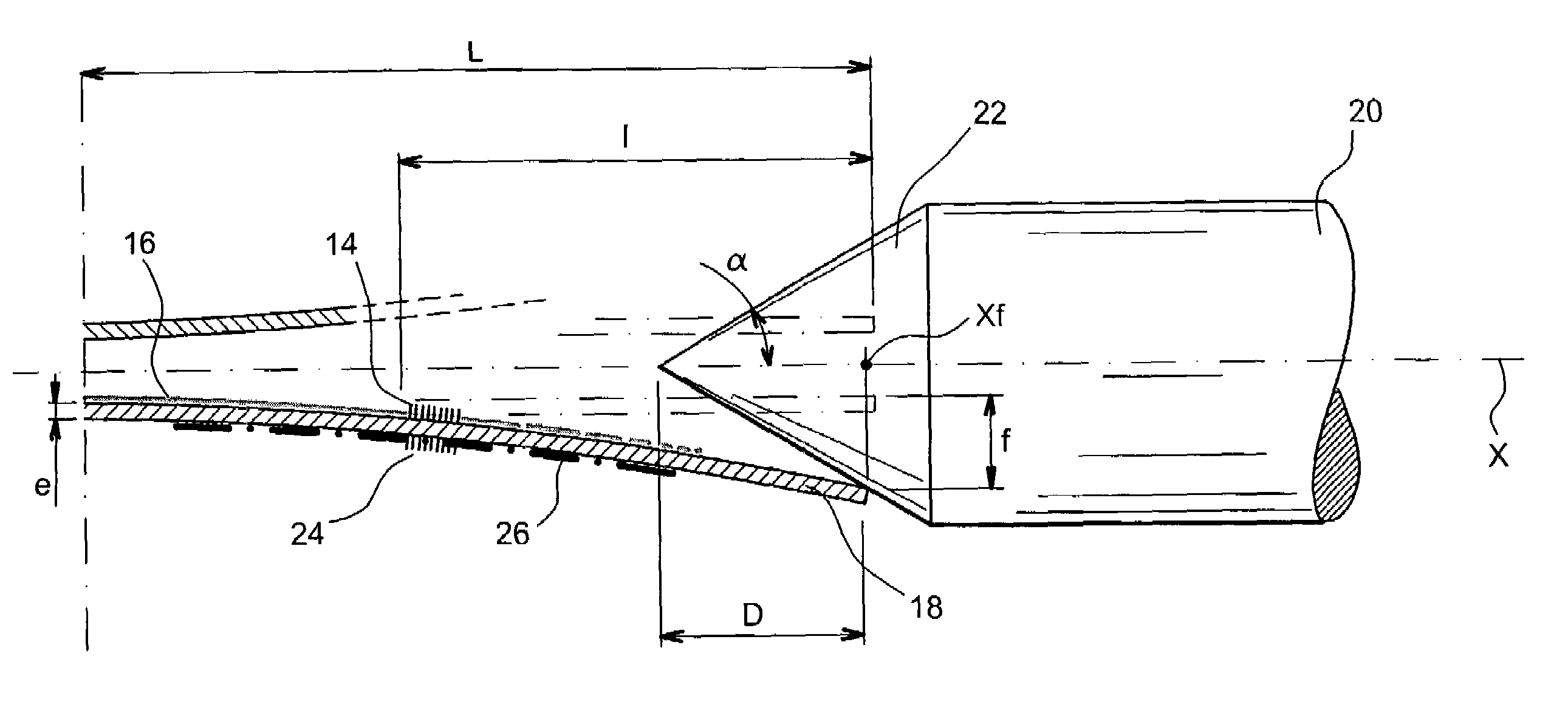
[0022]The object of the present invention is to remedy the preceding disadvantages by proposing an extensometer having greater measuring dynamics than extensometers with optic fibre and Bragg grating bonded onto a test specimen, which is directly subjected to the magnitude to be measured or stretched between two points. This extensometer also has improved measuring linearity compared with the above-mentioned known extensometer with springs.
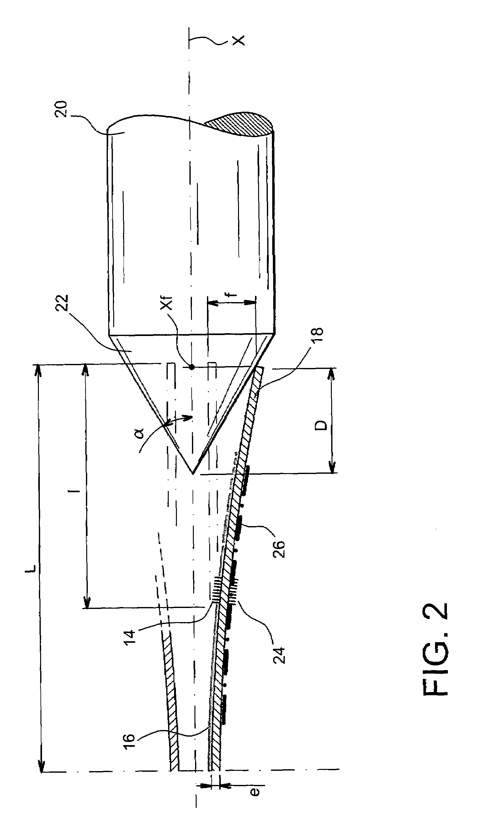
[0023]With the extensometer subject of the invention, it is possible to step down mechanically a displacement to be measured so as to remain within the range of use of the optic fibre or optic fibres it contains.
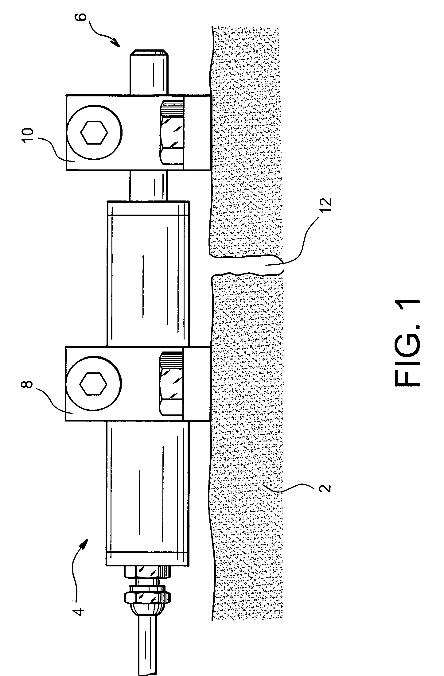
[0024]In addition, in preferred embodiments, it can compensate temperature effects and can be mounted in easy, reproducible manner which avoids systematic calibration of the sensor or sensors, i.e. of the Bragg grating(s) contained in this extensometer.
[0025]More precisely, the subject of the present invention is an extensometer intended t...
PUM
| Property | Measurement | Unit |
|---|---|---|
| length | aaaaa | aaaaa |
| length | aaaaa | aaaaa |
| Bragg wavelength | aaaaa | aaaaa |
Abstract
Description
Claims
Application Information