Rigid agitator and shaft assembly

Inactive Publication Date: 2007-02-06
AMERICAN IMAGING CARTRIDGE
View PDF3 Cites 4 Cited by
  • Summary
  • Abstract
  • Description
  • Claims
  • Application Information

AI Technical Summary

Benefits of technology

[0006]The long-standing but heretofore unfulfilled need for a toner cartridge that is adapted to be of an simplified construction, thereby limiting the number of elements required during manufacture, and which also includes improvements that overcome the limitations of prior art toner cartridges is now met by a new, useful, and non-obvious invention.
[0010]The agitator of the present invention includes angled and straight support members disposed between said agitator and said shaft. Each support member is equipped with a plurality of alternating angled tooth members disposed along a toner engaging surface of said support members. This configuration provides an optimum mixing surface for the toner. Additionally, the angled tooth members help to chip away toner which has become packed during non-use.
[0012]It is another object of the instant invention to provide a non-yieldable drive with fewer moving parts, which can fail, than that of the prior art. The additional parts required by the prior art pose numerous disadvantages, such as: higher cost associated with assembly and manufacture; the use of additional bushings; and failure due to binding of non-essential moving parts.

Problems solved by technology

Without the presence of the window, the printer would generate an error message which would cease operation of the printer.

Method used


Image

  • Rigid agitator and shaft assembly
  • Rigid agitator and shaft assembly
  • Rigid agitator and shaft assembly

Examples


Embodiment Construction

[0019]In the following detailed description of the preferred embodiments, reference is made to the accompanying drawings, which form a part hereof, and within which are shown by way of illustration specific embodiments by which the invention may be practiced. It is to be understood that other embodiments may be utilized and structural changes may be made without departing from the scope of the invention.

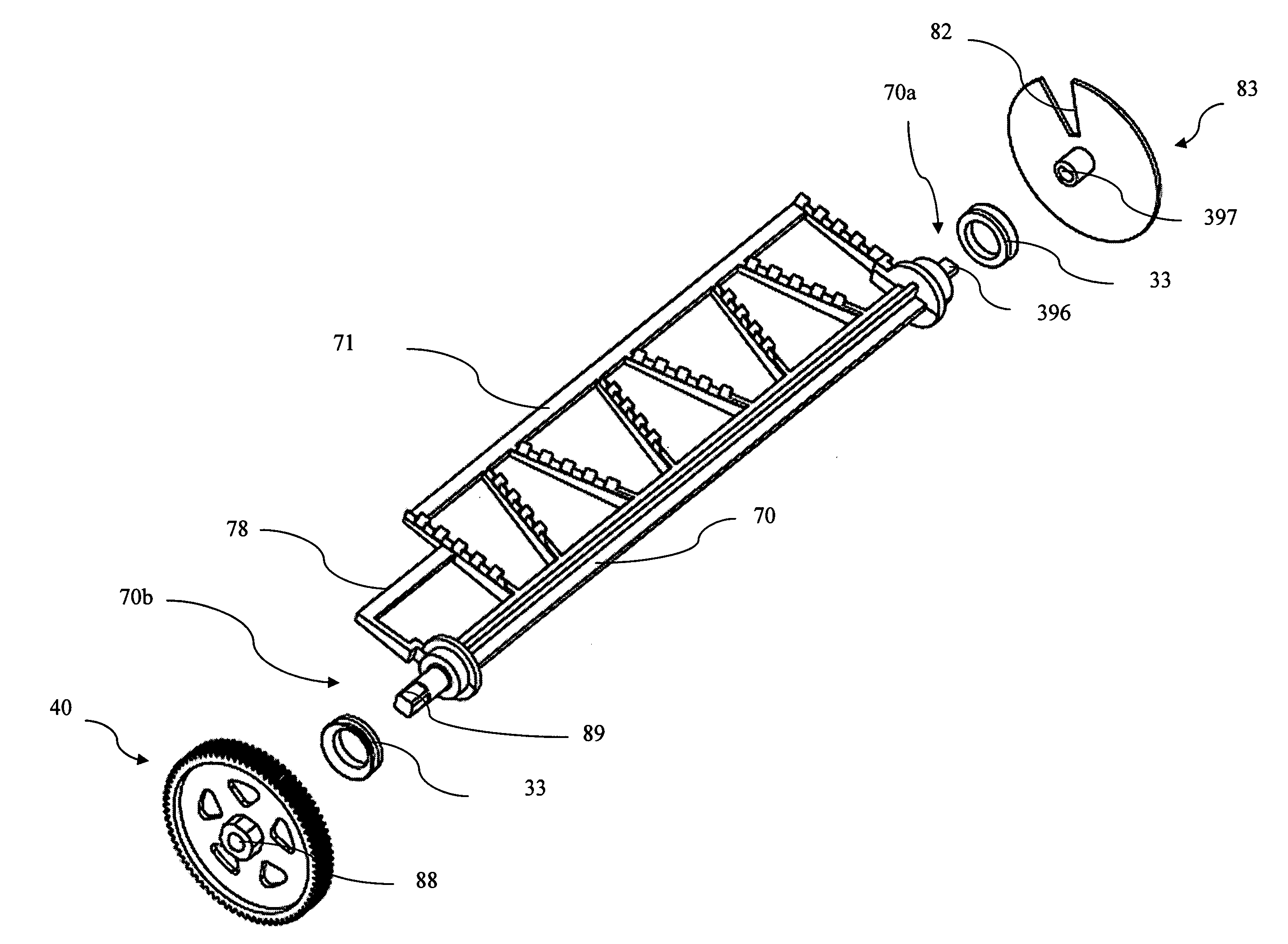
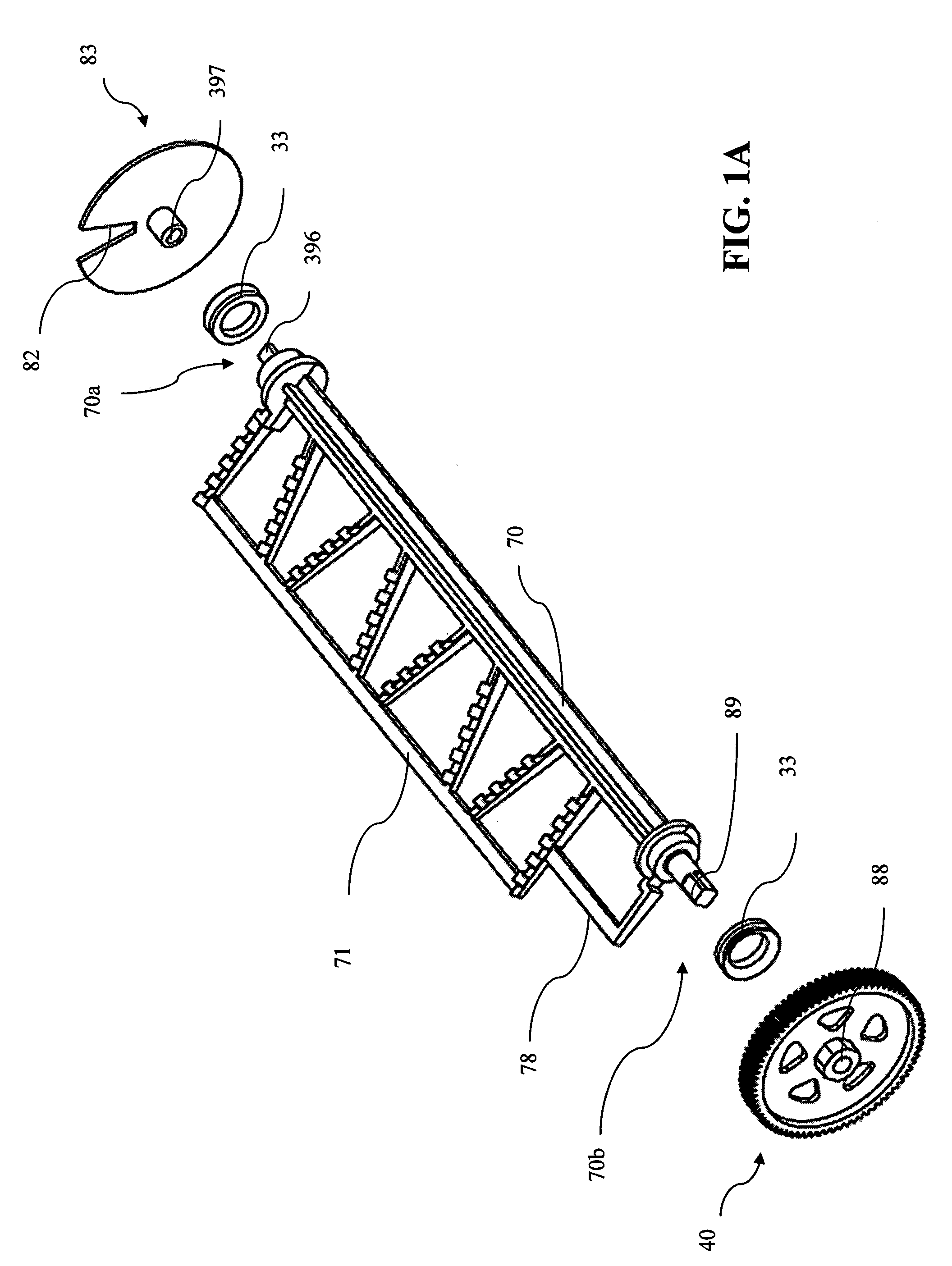
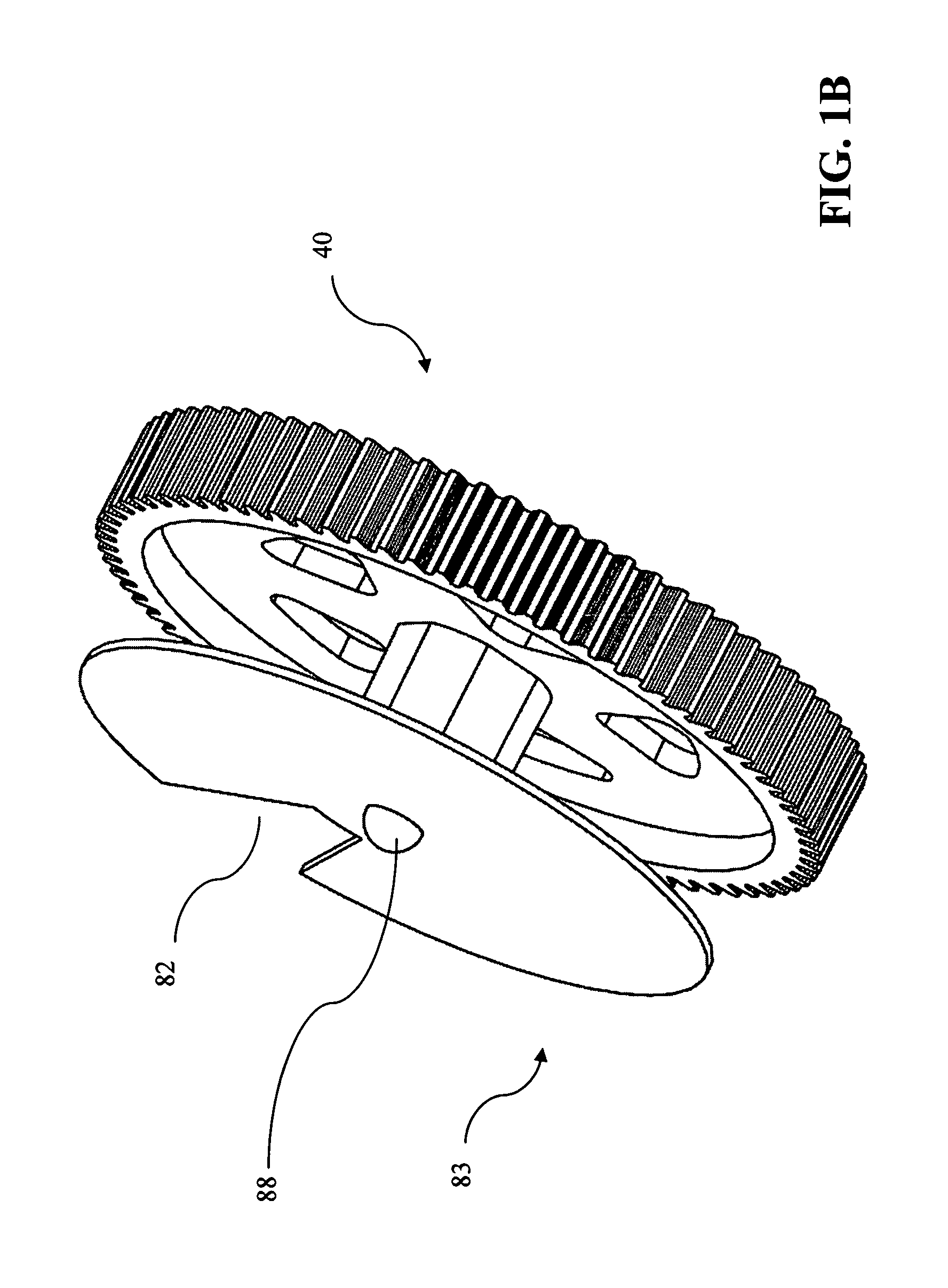
[0020]In a general embodiment the novel toner cartridge has a photoconductive drum on which an electrostatic image is formed. The photoconductive drum rotates in a plane perpendicular to that of the print medium passing through the toner cartridge. A recovery blade is placed in direct contact with the photoconductive drum. During the imaging stage, the photoconductive drum is exposed to light, usually a laser, which imprints a latent image thereon. A developing roller converts the electrostatic-image into a toner-image. Toner is then transferred to the print medium by means of static...


PUM


Abstract

A toner cartridge includes a waste bin and hopper designed with a rigid agitator assembly. A non-yieldable agitator is mounted on a shaft whereby the rotation of the shaft results in the synchronous rotation of the agitator. As the shaft rotates, the agitator enters into, through, and out of engagement with the toner within said toner chamber.

Description

CROSS REFERENCE TO RELATED APPLICATIONS[0001]This application is a continuation-in-part to co-pending U.S. patent application Ser. No. 10 / 907,470 entitled: “Integrated Toner Cartridge with Toner Agitator and Sensing Device,” filed Apr. 1, 2005, which is a continuation of U.S. patent application Ser. No. 10 / 742,323 entitled: “Removable Toner Cartridge Universal Adapter,” filed Dec. 19, 2003 now U.S. Pat. No. 7,136,608.BACKGROUND OF THE INVENTION[0002]Laser printers use a coherent beam of light, hence the term “laser printer,” to expose discrete portions of an image transfer drum thus attracting the printing toner. Toner is a mixture of pigment (most commonly black) and plastic particles. The toner becomes electrostatically attracted to exposed portions of the image transfer drum. The toner is transferred to paper, or other medium, as it passes over the rotating image transfer drum. Subsequently, the paper is heated so that the plastic is melted thereby permanently affixing the ink to...

Claims


Application Information

Patent Timeline
IPC IPC(8): G03G15/08G03G15/10
CPCG03G21/12G03G15/0877G03G15/0865G03G2215/0634G03G2215/0802
Inventor MILLER, STEVEN
Owner AMERICAN IMAGING CARTRIDGE
Why Eureka
Try Eureka