Methods and apparatus for requesting link state information

a technology of link state and information, applied in the field of link state routing, can solve problems such as network node disruption

Inactive Publication Date: 2007-02-06
CISCO TECH INC
View PDF15 Cites 120 Cited by
  • Summary
  • Abstract
  • Description
  • Claims
  • Application Information

AI Technical Summary

Benefits of technology

[0006]According to the present invention, methods and apparatus are provided for resynchronizing link state information in a network node. Information such as MAC addresses and system IDs of neighboring nodes can be stored in persistent memory and used to transmit heartbeat messages such as Hello messages after network node disruption. Network node disruption occurs, for example, when the routing control protocol running at a network node is restarted.

Problems solved by technology

Network node disruption occurs, for example, when the routing control protocol running at a network node is restarted.

Method used


Image

  • Methods and apparatus for requesting link state information
  • Methods and apparatus for requesting link state information
  • Methods and apparatus for requesting link state information

Examples


Embodiment Construction

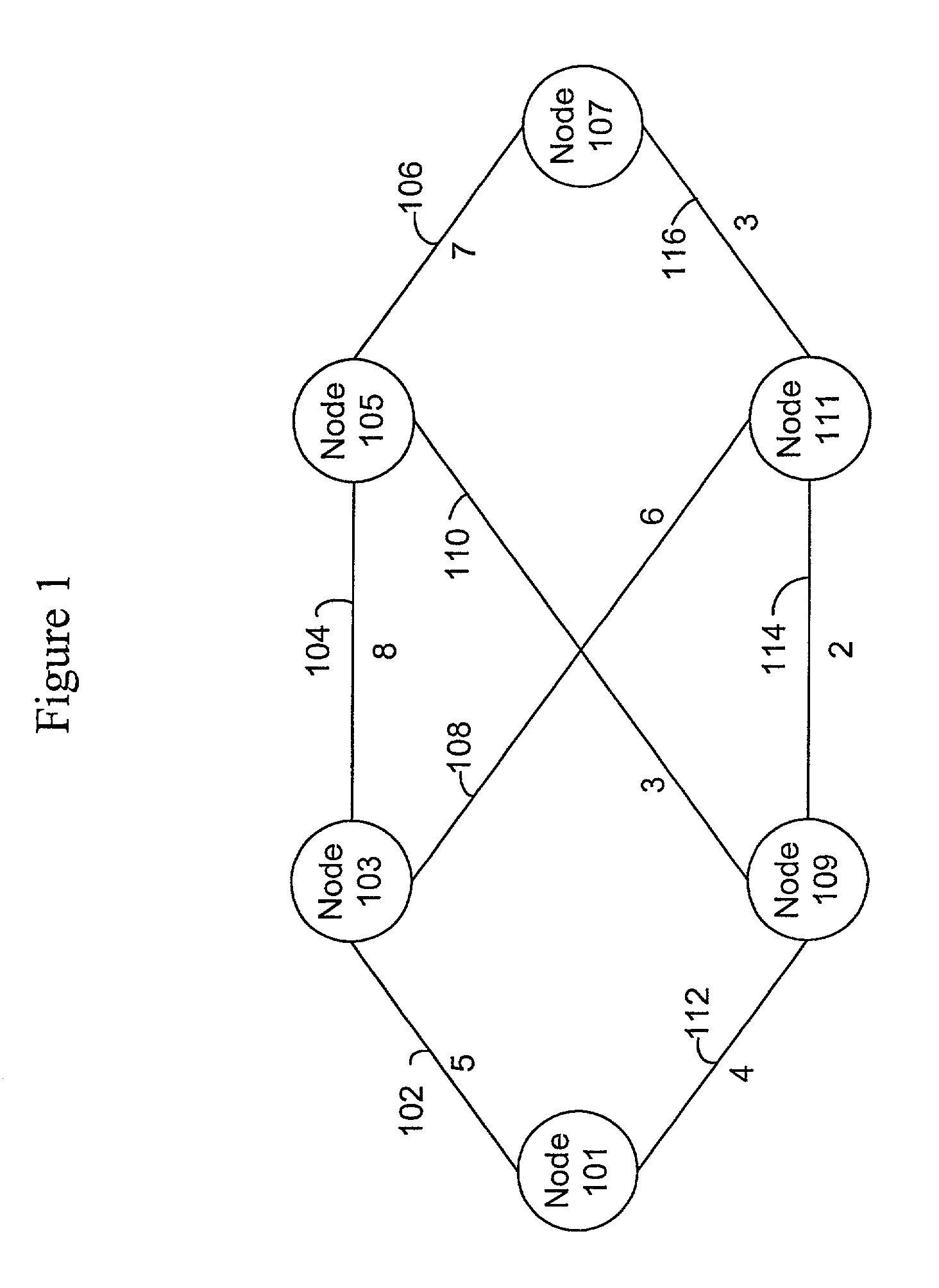
[0023]The present invention pertains to methods and systems for resynchronizing a link state database in a network node reintroduced into a network. FIG. 1 is a graph of a subnet showing one representation of network nodes connected by links associated with network metrics, according to specific embodiments. Each network node 101, 103, 105, 107, 109, and 111 can represent a router associated with a router table. Nodes are connected to other nodes through communication lines or links 102, 104, 106, 108, 110, 112, 114, and 116. For example, network node 101 is connected to node 103 through link 102. Each link is assigned a metric value. The metric value can be some function of distance, bandwidth, average traffic, communication cost, delay, or other type of cost. In FIG. 1, link 102 between nodes 101 and 103 is assigned a metric value of 5. Link 112 between nodes 109 and 101 is assigned a metric of 4. Typically, a lower assigned metric value would indicate a preferred link. To access ...


PUM


Abstract

Methods and apparatus are provided for optimizing the reintroduction of a network node into a network. Information about neighboring nodes is stored in persistent memory. The network node can then be reinitialized and reintroduced into the network. Upon reintroduction, the network node can transmit heartbeat messages such as Hello messages to its neighboring nodes using information stored in persistent memory. A link state packet request message such as a Complete Sequence Numbers Packet referencing dummy link state information is transmitted to a neighboring node. A partial packet request message such as a Partial Sequence Numbers Packet referencing the dummy link state packet from the neighboring node can acknowledge that the Complete Sequence Numbers Packet has been received.

Description

BACKGROUND OF THE INVENTION[0001]The present invention relates to link state routing. More specifically, the present invention relates to resynchonizing link state information using link state packets from neighboring nodes upon reintroducing a node into a network. Still more specifically, the present invention deals with a network node sending a message to a neighboring network node upon reintroducing the node into the network in order to receive link state packets from the neighboring node.[0002]A network graph is used to generate a routing table in a network node. The routing table allows a network node to determine what link an outbound packet should be transmitted on to move the packet closer to its destination. In order to generate a network graph, a network typically receives link state packets from the other nodes in a network. Each of the link state packets associated with a node contains information about the distance, delay, or cost from the node to one or more neighborin...

Claims


Application Information

Patent Timeline
Patent Type & Authority Patents(United States)
IPC IPC(8): G06F15/16G06F11/00G06F15/173
CPCH04L45/28H04L45/02H04L41/12H04L45/03
Inventor SHAND, IAN MICHAEL CHARLESSCHAEFER, MARK T.
Owner CISCO TECH INC
Why Eureka
Try Eureka