Pedal/cleat assembly

a technology of clipless pedals and clamps, applied in the field of pedals, can solve the problems of difficult adjustment and unsatisfactory provisions for adjusting the float range, and achieve the effect of easy and precise adjustmen

Active Publication Date: 2007-02-13
WAHOO FITNESS LLC
View PDF24 Cites 38 Cited by
  • Summary
  • Abstract
  • Description
  • Claims
  • Application Information

AI Technical Summary

Benefits of technology

[0006]The present invention is embodied in an improved pedal / cleat assembly that provides a float range that is easily and precisely adjustable. The pedal / cleat assembly includes a cleat assembly configured for attachment to the underside of a rider's shoe, and a pedal assembly configured to releasably secure the cleat assembly. The cleat assembly includes (1) a first body that defines forward and rearward projections arranged in a prescribed, fixed relationship to each other, (2) a second body configured to be attached to the underside of the rider's shoe and to be secured to the first body, for limited rotation relative to the first body about a cleat rotation axis, and (3) a stop mechanism carried by the first and second bodies, for limiting rotation of the second body relative to the first body. The pedal assembly includes (1) a rotatable spindle, (2) a main pedal body mounted for rotation on the spindle and having an upper side configured for engagement with the cleat assembly, and (3) forward and rearward cleat retainers projecting upwardly from the upper side of the main pedal body, on opposite sides of the spindle. The forward and rearward cleat retainers are sized and configured to be forcibly retractable apart from each other, so as to receive and retain the respective forward and rearward projections of the cleat assembly, to secure the cleat assembly to the pedal assembly. In addition, rotation of the second body of the cleat assembly, about the cleat rotation axis and beyond the limit provided by the stop mechanism, forcibly retracts the forward and rearward cleat retainers apart from each other, to release the cleat assembly from the pedal assembly.
[0007]More particularly, the stop mechanism of the cleat assembly includes a pair of first stop surfaces defined on the first cleat body, and a pair of second stop surfaces defined on the second cleat body. The second cleat body is freely rotatable relative to the first cleat body, about the cleat rotation axis, until one of the second stop surfaces engages one of the first stop surfaces, whereupon further relative rotation is prevented. In one embodiment, the pair of second stop surfaces is defined by a finger projecting radially outward from the second cleat body, and the pair of first stop surfaces is defined by two set screws adjustably mounted on the first cleat body. Adjustment of the set screws modifies the amount of free clockwise and counterclockwise rotation of the second cleat body relative to the first cleat body.

Problems solved by technology

In general, however, provisions for adjusting the float range have not been entirely satisfactory.
In some cases, the adjustments could be made only in large increments, while in other cases, the adjustments have been difficult to perform.

Method used


Image

  • Pedal/cleat assembly
  • Pedal/cleat assembly
  • Pedal/cleat assembly

Examples


first embodiment

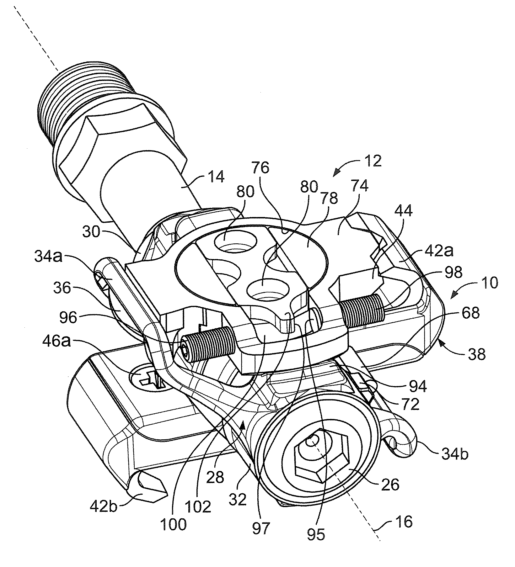
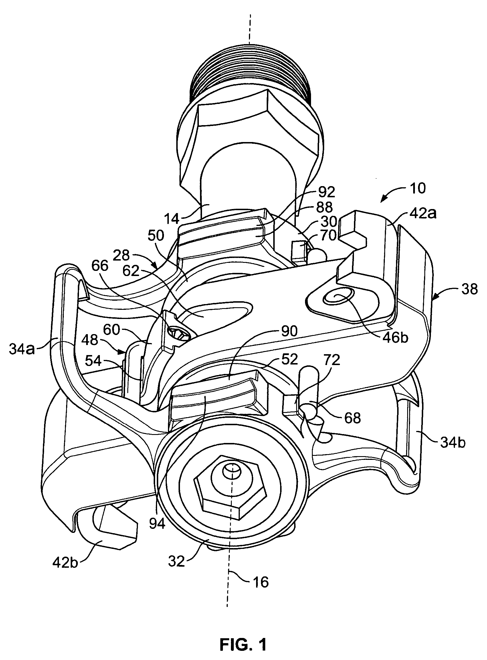
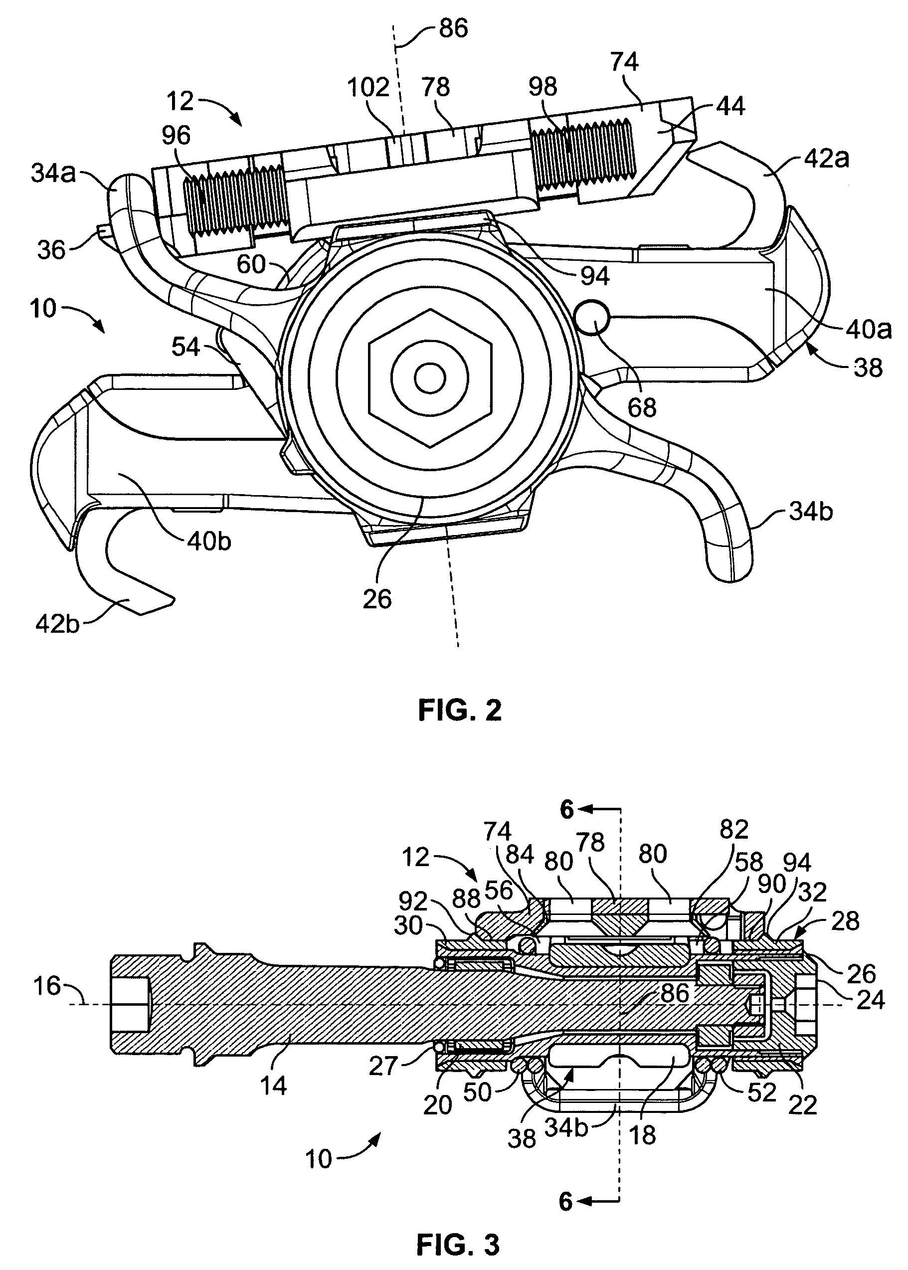
[0023]With reference now to the illustrative drawings, and particularly to FIGS. 1–4 and 6, there is shown a bicycle pedal / cleat assembly in accordance with the invention, including a pedal assembly 10 and an associated cleat assembly 12. The cleat assembly is secured to the underside of the sole of a rider's shoe (not shown), and it is configured to be attachable to the pedal assembly in a manner that allows limited rotational movement, but to be released from that attachment if the rotational movement exceeds a selected angular amount. Only a left-side pedal assembly is shown in the drawings and discussed below, although it will be understood that a similar, mirror-image pedal assembly can be located on the bicycle's right side.

[0024]More particularly, the pedal assembly 10 includes an elongated spindle 14 that projects laterally from a bicycle crank (not shown). The spindle is rotatable about a spindle axis 16 oriented to be parallel with the crank's rotation axis. A bearing slee...

second embodiment

[0038]FIGS. 7–9 depicts a cleat assembly 104 in accordance with the invention, suitable for use with the pedal assembly 10 of FIGS. 1–6. The cleat assembly 104 includes a first disc-shaped cleat body 106 having two circular openings 114a, 114b for receiving attachment screws (not shown) that can be used to attach the body to the underside of the sole of a rider's shoe (not shown), for engagement with, and retention by, the respective forward and rearward cleat retainers 34 and 42 of the pedal assembly. The cleat assembly further defines a second disc-shaped cleat body 112 defining a forward projection 108 and a rearward projection 110. The second cleat body 112 is configured to be secured to the first cleat body 106, for limited rotation about a cleat rotation axis. Access to the attachment screws that attach the first cleat body 106 to the rider's shoe is provided by enlarged openings 118a, 118b (FIG. 8) formed in the second cleat body 112.

[0039]More particularly, the first disc-sh...

third embodiment

[0042]FIGS. 10 and 11 depict a cleat assembly 138 in accordance with the invention, suitable for use with the pedal assembly 10 of FIGS. 1–6. The cleat assembly 138 includes a main cleat body 140 that defines a forward projection 142 and a rearward projection 144, configured for engagement with, and retention by, the respective forward cleat retainer 34 and rearward cleat retainer 42 of the pedal assembly. The main cleat body 140 also defines an open interior configured to receive an elongated insert 146 in an orientation generally transverse to a longitudinal axis defined by the forward and rearward projections. The insert includes three lobes: a central lobe 148 formed in the shape of a disc having two arcuate sidewalls 150a and 150b, and the insert further includes two end lobes 152a, 152b (or second stop surfaces 147) located on opposite sides of the central lobe. The main cleat body 140 includes a rib 154 extending longitudinally across its open interior, for supporting the ins...


PUM


Abstract

An improved pedal / cleat assembly provides a float range that is easily and precisely adjusted. The pedal / cleat assembly includes a pedal assembly incorporating a forward cleat retainer and a spring-biased rearward cleat retainer, and it further includes a cleat assembly that defines forward and rearward projections sized and configured to engage and be retained by the respective forward and rearward cleat retainers. The cleat assembly includes a first cleat body that defines the forward and rearward projections, and it further includes a second cleat body configured to be attached to the underside of a rider's shoe and to be secured to the first cleat body in a manner that allows limited rotation relative to the first cleat body about a cleat rotation axis. The first cleat body is free to rotate by an angular amount that is controlled by a pair of set screws. This provides a pedal float that is easily and precisely adjustable.

Description

BACKGROUND OF THE INVENTION[0001]This invention relates generally to pedals for use on bicycles and the like, and, more particularly, to clipless pedal / cleat assemblies in which a cleat attached to a rider's shoes can be releasably secured to a pedal.[0002]Clipless pedals of this particular kind commonly include forward and rearward cleat retainers mounted on the pedal's upper side. These cleat retainers are configured to be forcibly retractable apart from each other, against the yielding bias of a spring mechanism, to receive and releasably secure forward and rearward projections that are part of a cleat attached to the sole of a rider's shoe. The rider can release the cleat and shoe from the pedal simply by rotating the shoe by a predetermined angular amount, about an axis perpendicular to the pedal's upper side. This causes cam surfaces on the cleat to engage the forward and rearward cleat retainers and forcibly urge the cleat retainers apart from each other, against the yielding...

Claims


Application Information

Patent Timeline
Patent Type & Authority Patents(United States)
IPC IPC(8): B62M3/00G05G1/30
CPCB62M3/086Y10T74/2168Y10T74/217
Inventor BRYNE, RICHARD M.
Owner WAHOO FITNESS LLC
Why Eureka
Try Eureka