

Clockwise or counterclockwise rotation control device of a pneumatic tool
- Summary
- Abstract
- Description
- Claims
- Application Information
AI Technical Summary
Benefits of technology
Problems solved by technology
Method used
Image

Examples
Embodiment Construction
[0010]The present invention will now be described in more detail hereinafter with reference to the accompanying drawings as follows:
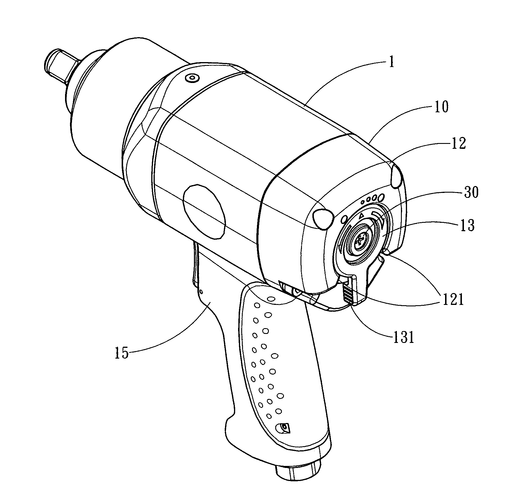
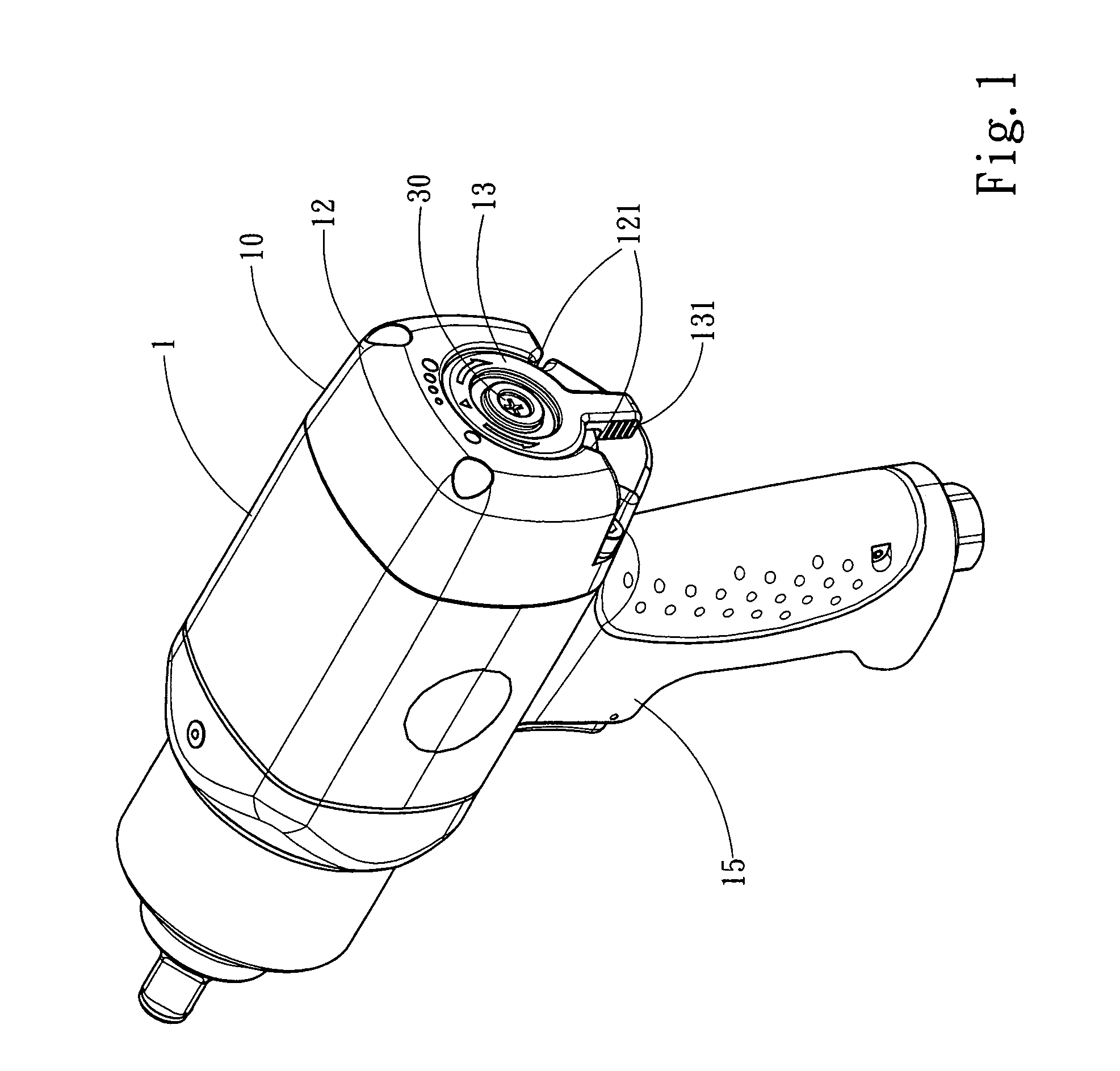
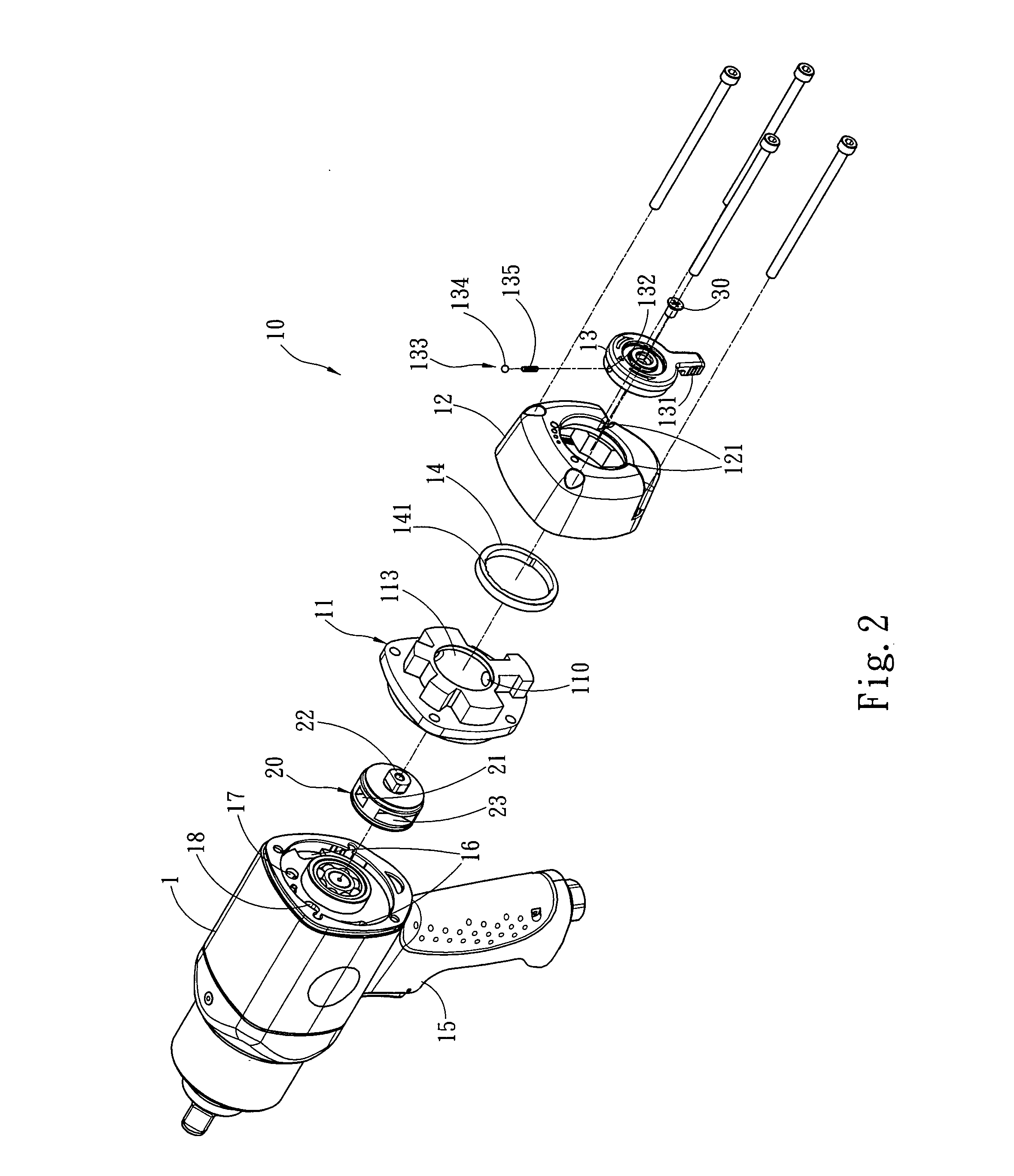
[0011]Referring to FIGS. 1 to 3 for the perspective view, the exploded view, and the cross-sectional view of the present invention, a clockwise or counterclockwise rotation control device of a pneumatic tool in accordance with the invention is installed at the rear end of a pneumatic tool, such that the pressurized air passes through and drives a pneumatic motor module of the pneumatic tool to move, so as to achieve the control of the pneumatic tool to produce a clockwise or counterclockwise rotation by changing the position of the pneumatic motor module. The pneumatic tool comprises a main body 1, a holding portion 15 coupled to the bottom of the main body 1, and a pneumatic motor module (not shown in the figure) installed in the main body 1. After the pressurized air passes through the clockwise or counterclockwise rotation control device in the pneum...
PUM
 Abstract
Description
Claims
Application Information