
Screw driven hoist

a technology of screw drive and hoist, which is applied in the field of hoist, can solve the problems of lack of precision of electric hoist, and achieve the effect of moving and positioning loads very accurately and high mechanical advantages of hois

Inactive Publication Date: 2007-02-13
RATCLIFF BRUCE E
View PDF11 Cites 29 Cited by
  • Summary
  • Abstract
  • Description
  • Claims
  • Application Information

AI Technical Summary

Benefits of technology

[0006]The tension members can be wire cables, coil chains, synthetic webbing straps, or other appropriate strong and flexible tension members. These tension members apply force to a load and, with the high mechanical advantage of the hoist, can move and position a load very accurately.
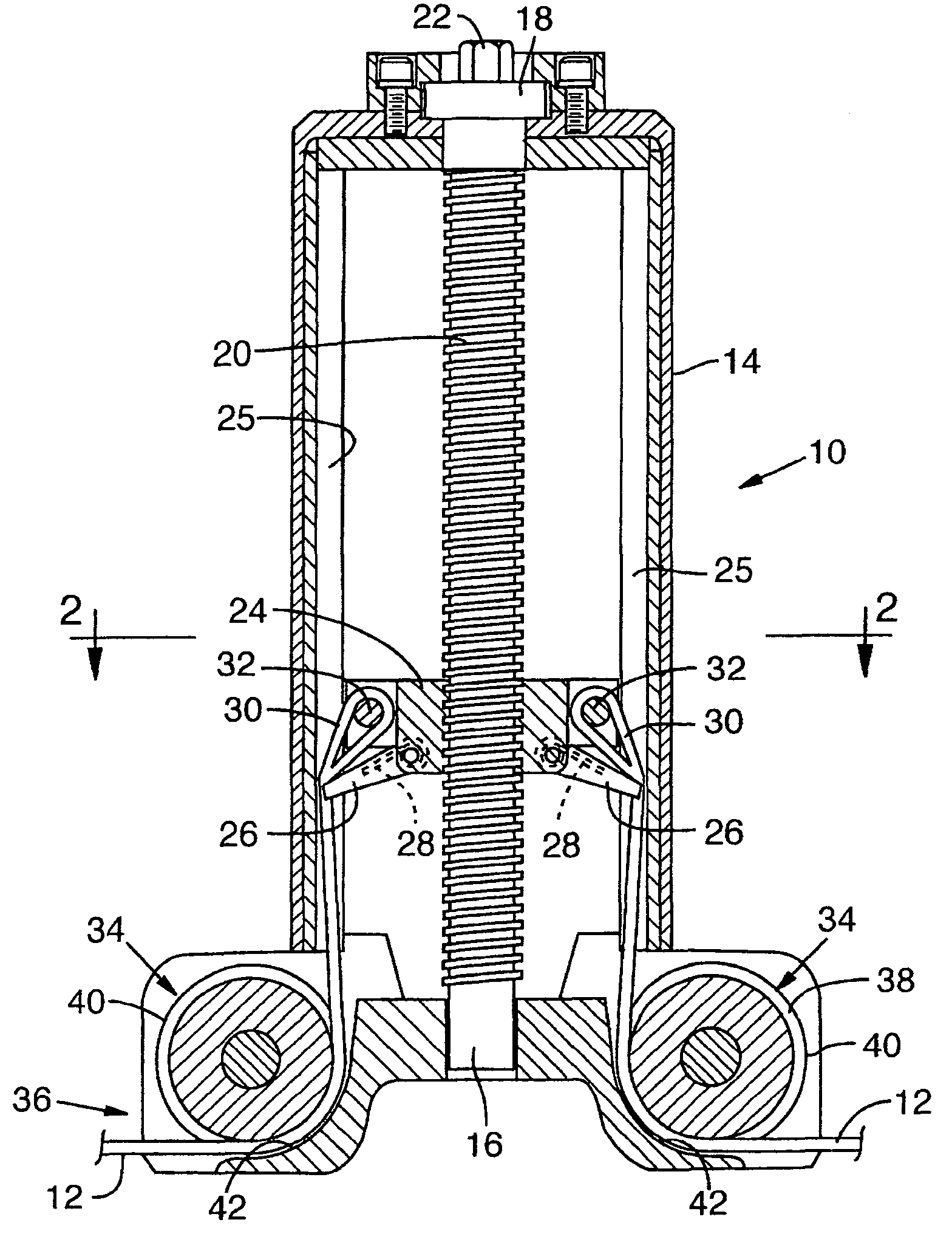
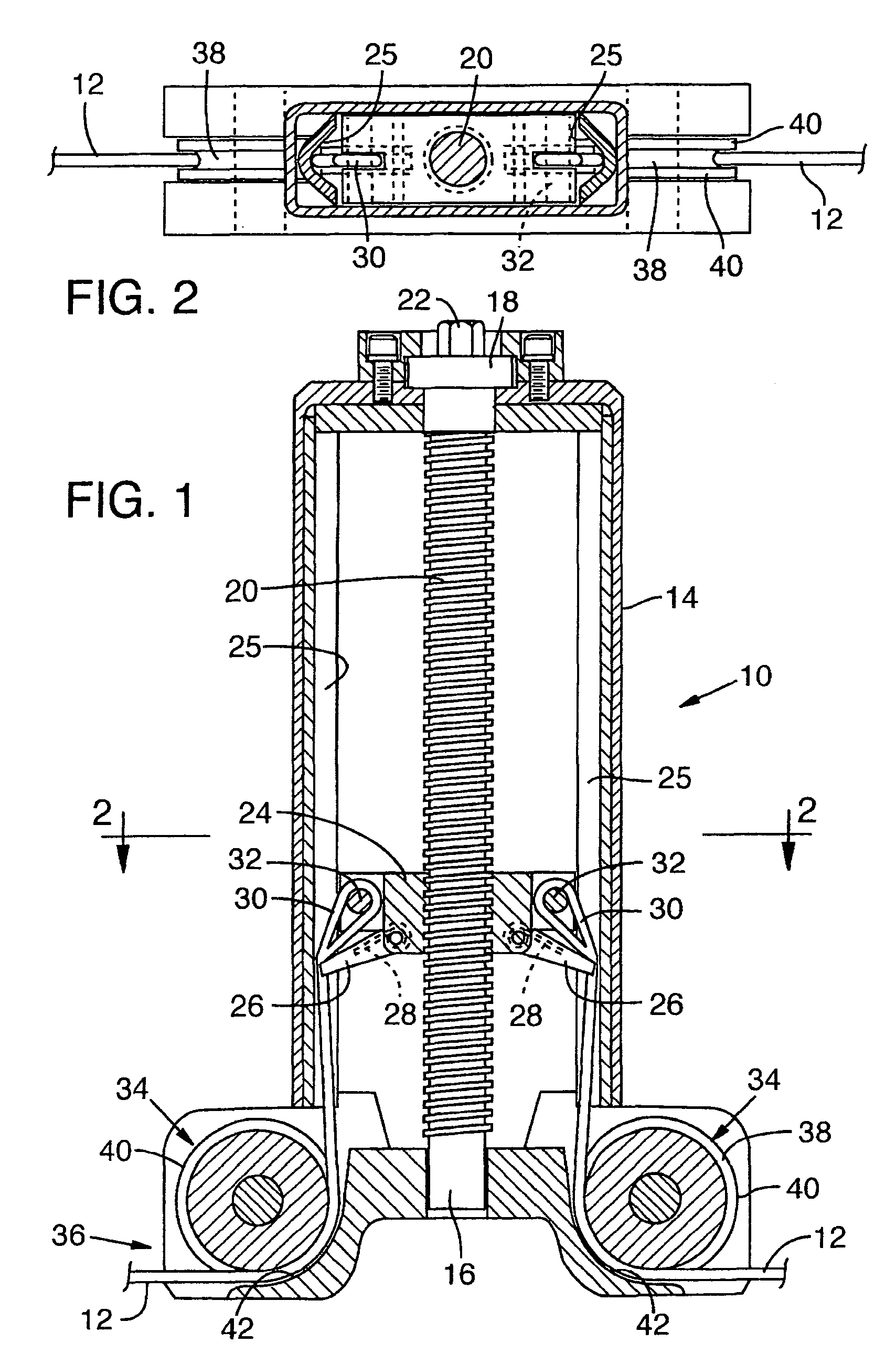
[0007]In one form of the invention, a pair of cables, or four or more cables, are secured to a load nut gear within the housing of the tool and pass over cable idler pulleys to extend in opposite directions from the housing. Guides for the cables comprise V grooves extending longitudinally in the housing, and preferably with a spring-biased means for pushing the cable into the V groove to maintain the cables in an orderly fashion in the housing, without kinking or twisting, when the wire cables are not in tension. Stationary pulley guides are located in close proximity to the edges flanges of the cable pulleys so that the cables cannot twist out of the pulley groves when not in tension.
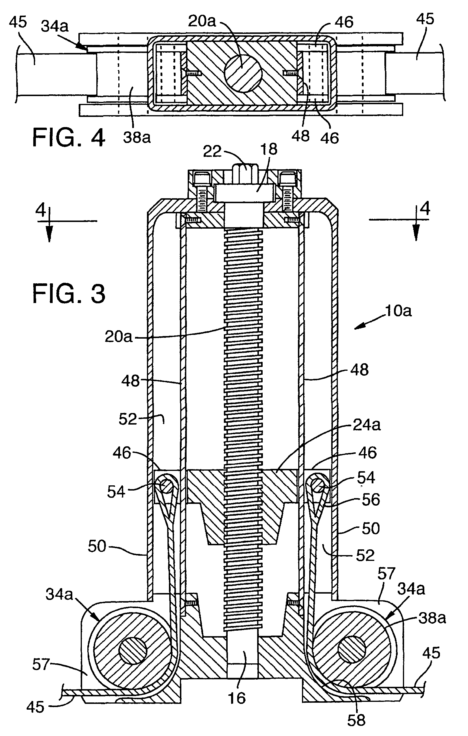
[0009]In another embodiment of the invention, coil chains are used, one in each side of the housing. Such coil chains generally comprise welded racetrack-shaped links which are interlinked in alternating orientations, the type used for log chains, many chain hoists and other heavy duty applications. In this case the pulleys of the cable embodiment are replaced with idler sprockets designed to smoothly engage with this type of chain. For guidance of chains within the housing, guide channels are provided at each side of the housing, closely guiding each chain within the housing, and with guides actually passing through the nut. The load nut has arms from which pins extend into and through the guide channels, engaging the end links of the chains. When the screw gear is back-rotated to pay chain out of the housing, the guide channels prevent bunching, kinking, or jamming and keep the chains in orderly arrangement for feeding out over the idler sprockets to the exterior of the housing.

Problems solved by technology

The electric hoist lacks precision, and use of the screw hoist enables very precise final adjustment of position of a heavy load.

Method used


Image

  • Screw driven hoist
  • Screw driven hoist
  • Screw driven hoist

Examples


Embodiment Construction

[0022]FIGS. 1 and 2 show a screw gear hoist 10 of one embodiment of the invention, in this case utilizing wire rope, also known as wire cable or cable, as the tension members 12 of the hoist. In this form of the invention, a housing 14 provides a frame for the device and is generally elongated in shape as shown, providing bearings 16 and 18 at opposite ends for rotation of a screw gear or load screw 20 within the housing. The bearing 18 is a thrust bearing, only schematically shown in the drawings. Typically this will be a cylindrical roller thrust bearing. At a first end of the load screw is a tool head 22 for engagement by a tool for rotational input to the device. This could be a hand tool or a power tool such as a drill, for example. Threadedly connected to the load screw is a load nut 24, which moves in a longitudinal direction, with great mechanical advantage, when the load screw 20 is rotated.

[0023]In this embodiment the wire ropes or cables 12 are guided within the housing s...


PUM

PropertyMeasurementUnit
Lengthaaaaaaaaaa
Lengthaaaaaaaaaa
Forceaaaaaaaaaa

Abstract

A hoist provides high mechanical advantage and accurate positioning, driven by hand or with a powered rotary implement such as a drill. The hoist includes flexible tension members, such as chains, cables or straps, for applying force and tension to a load. A load nut is connected to the tension members for high mechanical advantage from rotational drive input to a load screw threadedly connected to the load nut. Alongside the tension members are guides forming channel-like spaces within which the flexible tension members travel. The guides, or portions of the guides, pass through the load nut in most forms of the invention.

Description

BACKGROUND OF THE INVENTION[0001]This invention concerns a hoist which receives a rotational input and applies tension to a pair of opposed flexible tension members with very high mechanical advantage. Hoists of this type include a screw gear which provides a positive hold of the applied tension force when the screw gear is not being driven.[0002]Screw gear hoists are known. The applicant's own U.S. Pat. No. 5,971,178 shows a hoist of this type employing link-and-pin type chains (roller chains) drawn by a load nut or nut gear which is translated by a load screw or screw gear having a connection for receiving rotary input from a pneumatically powered impact tool or from a hand-powered tool.[0003]Hoists of this type, with high mechanical advantage, can be used for lifting or repositioning a heavy load, for fine positional adjustment, or for load binding. Often they can be used in combination with an overhead electric hoist, secured to the bottom hook of such a hoist. The electric hois...

Claims


Application Information

Patent Timeline
IPC IPC(8): B65H77/00
CPCB66D3/18
Inventor RATCLIFF, BRUCE E.
Owner RATCLIFF BRUCE E
Learn More