Latch with shipping condition

a technology of latches and shipping conditions, applied in the field of latches with shipping conditions, can solve the problems of inability to adjust the rigid rod and the lack of useful functions of the spring, and achieve the effect of reducing increasing the biasing force on the lever

Inactive Publication Date: 2007-02-13
INTIER AUTOMATIVE CLOSURES INC
View PDF12 Cites 10 Cited by
  • Summary
  • Abstract
  • Description
  • Claims
  • Application Information

AI Technical Summary

Benefits of technology

[0009]According to another aspect of the invention, a vehicle latch is provided having a housing with a detent and a stop. A lever is pivotally connected to the housing and is movable from a ready position engaging the housing to an active position pivoted away from the housing. A spring extends from the lever to the housing applying a biasing force to the lever urging the lever to the ready position. The spring has a tail portion, a coil section and an opposite end. The opposite end engages the lever to provide the biasing force which moves the lever to the ready position. The tail end is moveable to engage either the stop or detent. When the tail end engages the detent, the tail end also engages the lever and the biasing force holding the lever in the ready position is increased. The tail end is removable from the detent to engage the stop when the lever is first pivoted away from the ready position, disengaging the lever from the tail end and thus reducing the biasing force on the lever.

Problems solved by technology

However, a rigid rod cannot be adjusted after the clip connecting the release lever to the rod has been closed.
If the release lever is unable to return to the designed rest or ready position, the release lever may block or prevent the locking lever from freely moving preventing the latch from fully locking or unlocking.
However, in normal operation, the spring provides no useful function.

Method used


Image

  • Latch with shipping condition
  • Latch with shipping condition
  • Latch with shipping condition

Examples


Embodiment Construction

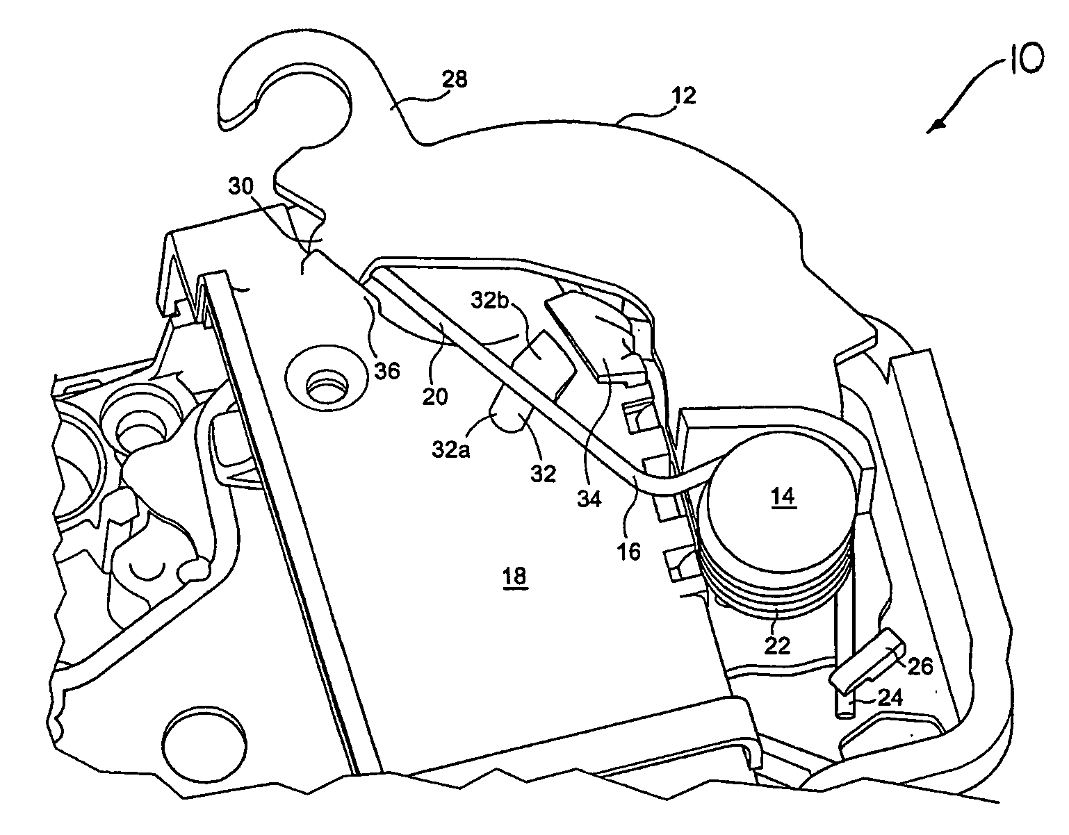
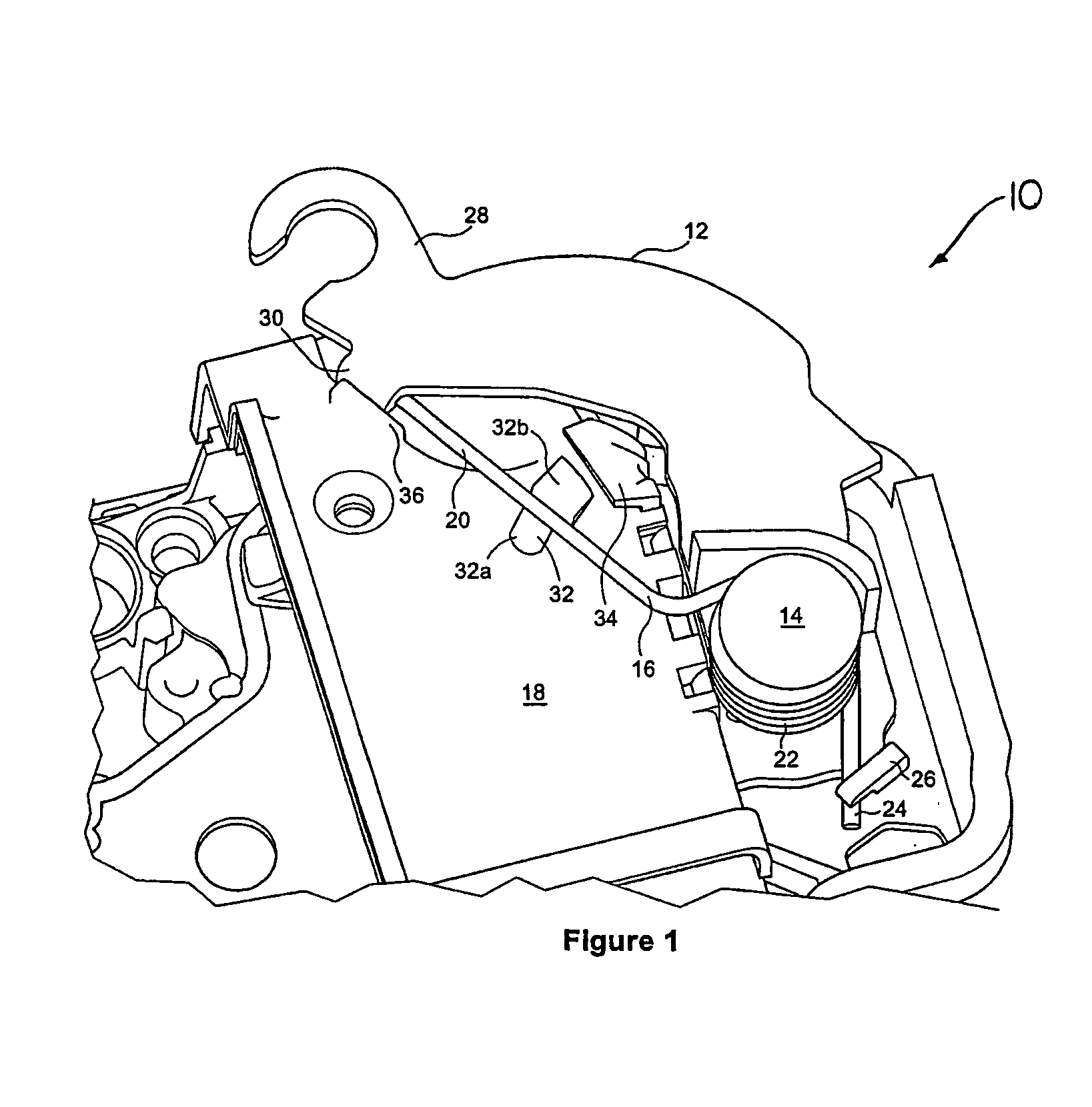
[0014]FIG. 1 illustrates a latch 10 of the present invention. The latch 10 is of conventional construction and design. Typically, latch 10 can have four levers, an inside and outside locking lever and an inside and outside release lever. Although the invention could be applied to any of these levers, the invention is preferably applied to the outside release lever for an operative connection to an outside door handle.

[0015]The latch 10 has a lever 12 that is pivotally connected to the latch 10 at pin 14. A spring 16 extends between the lever 12 and the housing 18 of the latch 10. Spring 16 has an elongated tail portion 20 extending from a coil section 22 wound about the pin 14, terminating in an opposite end 24. End 24 engages a tab 26 of lever 12. The tail portion 20 of the spring 16 engages a connecting end 28 of the lever 12 at an abutment or tab 30.

[0016]Housing 18 has a detent 32, preferably formed from two wedge shaped parts 32a, 32b molded in the face of the housing, and a st...


PUM


Abstract

A vehicle latch has a housing with a detent and a stop. A lever is pivotally connected to the housing and movable from an install position engaging the housing to an active position pivoted away from the housing. A spring extends from the lever to the housing applying a biasing force to the lever urging the lever to the install position. The spring has a tail portion, a coil section and an opposite end. The opposite end engages the lever. The tail end is moveable to engage either the stop or detent. In the install position, the tail end engages the detent and also engages the lever. In this position, the spring increases the biasing force holding the lever in the install position. The tail end is removable from the detent to engage the stop when the lever is first pivoted away from the install position. This disengages the tail end from the lever and also reduces the biasing force on the lever.

Description

FIELD OF THE INVENTION[0001]This invention relates to a vehicle latch that can hold a lever, in particular a release lever, during shipping and installation.BACKGROUND OF THE INVENTION[0002]Vehicle latches generally comprise a housing, a ratchet, a pawl, an inside release lever, an outside release lever, an inside locking lever, and an outside locking lever. The various levers are operably coupled to the pawl to effect the various functions of the latch. Examples of typical latches are disclosed in U.S. Pat. Nos. 4,929,007 and 6,254,148.[0003]Each of the various levers are operably connected, typically via a Bowden cable or rigid rod, to a respective handle or lever. A Bowden cable can be adjusted after the lever is installed. However, a rigid rod cannot be adjusted after the clip connecting the release lever to the rod has been closed. If the release lever is not in the correct position for installation, the attachment of the release lever to the clip will leave the release lever i...

Claims


Application Information

Patent Timeline
Patent Type & Authority Patents(United States)
IPC IPC(8): E05C3/06E05B3/00E05B17/00E05B65/20
CPCE05B17/0012E05B83/36Y10S292/64Y10S292/61Y10S292/23Y10T292/1047Y10T292/1082
Inventor CETNAR, ROMANTOMASZEWSKI, KRISPAWLUS, JOZEF
Owner INTIER AUTOMATIVE CLOSURES INC
Why Eureka
Try Eureka