Tube style cosmetic container structure

a cosmetic container and tube-type technology, applied in the field of tube-type cosmetic container structure, can solve the problems of cosmetic liquid being polluted and quality degraded, inconvenient to use, air pollution affecting quality, etc., to prevent liquid backflow, prevent cosmetic and prevent liquid from being polluted

Active Publication Date: 2007-02-13
CHUEN CHERN
View PDF5 Cites 14 Cited by
  • Summary
  • Abstract
  • Description
  • Claims
  • Application Information

AI Technical Summary

Benefits of technology

[0006]Thus, the main objective of the invention is to provide a tube style cosmetic container structure that can prevent liquid overflow when its exterior cap is tightly screwed on, can prevent liquid backflow when its exterior cap is screwed off for usage, and can also prevent cosmetic liquid being polluted by air.
[0007]In addition, another objective of the invention is to provide a tube style cosmetic container structure that facilitates squeezing by a user and, thus, has advantage in usage.
[0015]When the exterior cap is screwed on, the material discharge hole will be wholly blocked, and no liquid will overflow from the material discharge hole even when the tube is under certain pressure. When the exterior cap is screwed off and the tube is squeezed to force the contents out, no squeezed contents will backflow even when the pressure is reduced or stopped. Thus, the tube can not only be used conveniently but can isolate air pollution and, thus, has advantage in usage.

Problems solved by technology

Therefore, the cosmetic pencil has to be used in a rotational way that complicates its application, and the cosmetic liquid might be polluted and quality degraded due to contacting air.
According to above description, the known cosmetic pencil has such defects that it is inconvenient to use and is liable to air pollution that affects quality.

Method used


Image

  • Tube style cosmetic container structure
  • Tube style cosmetic container structure
  • Tube style cosmetic container structure

Examples


Embodiment Construction

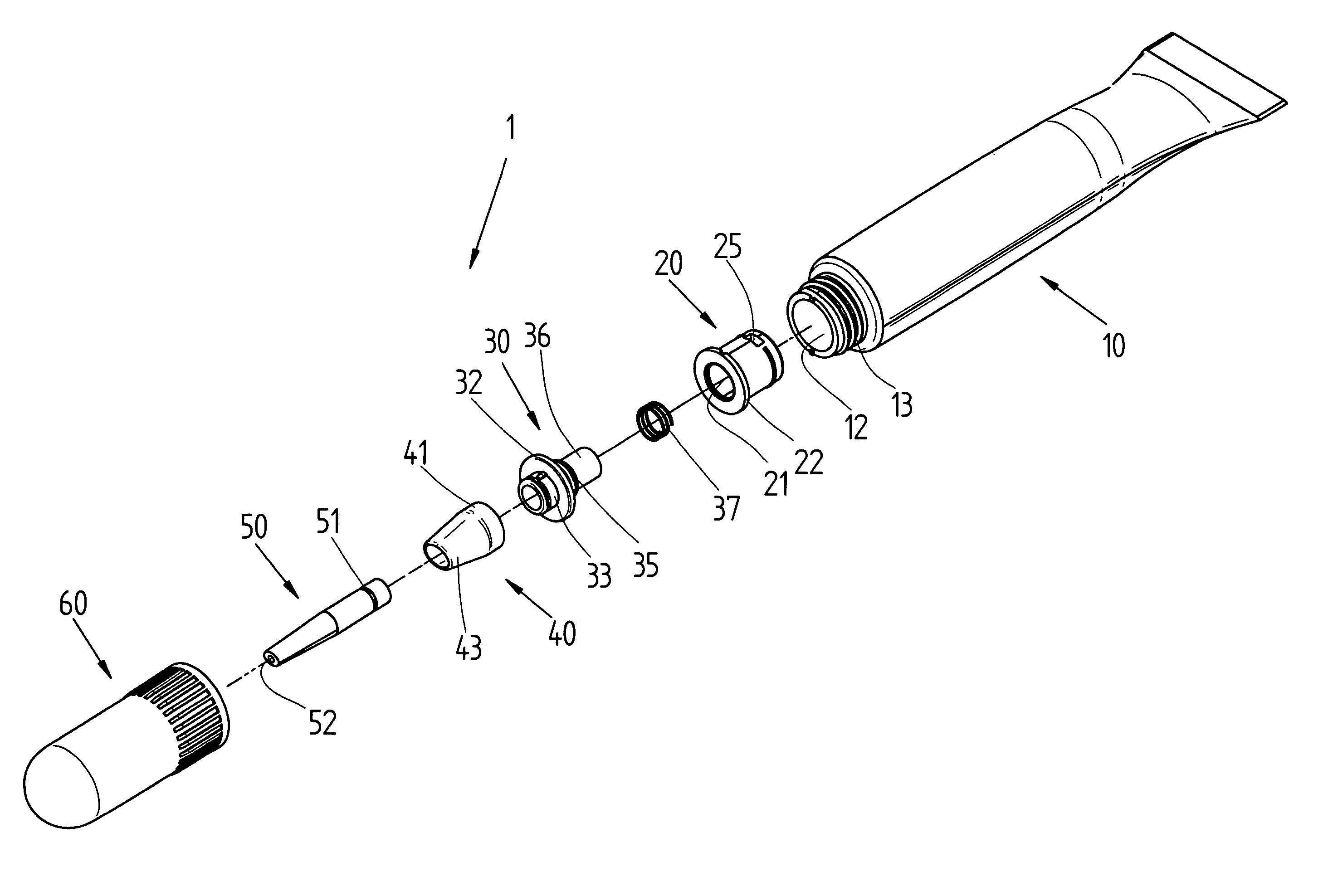
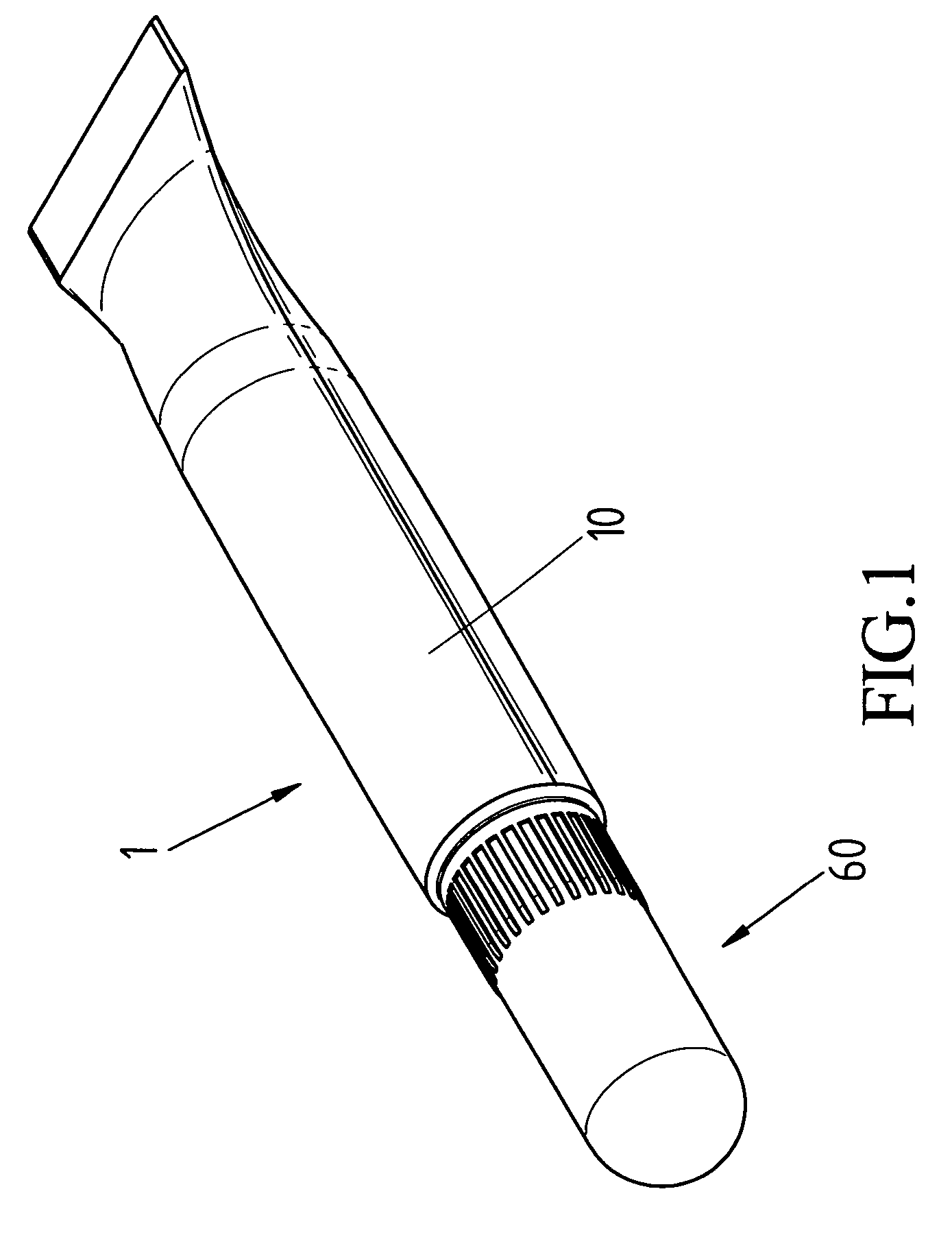
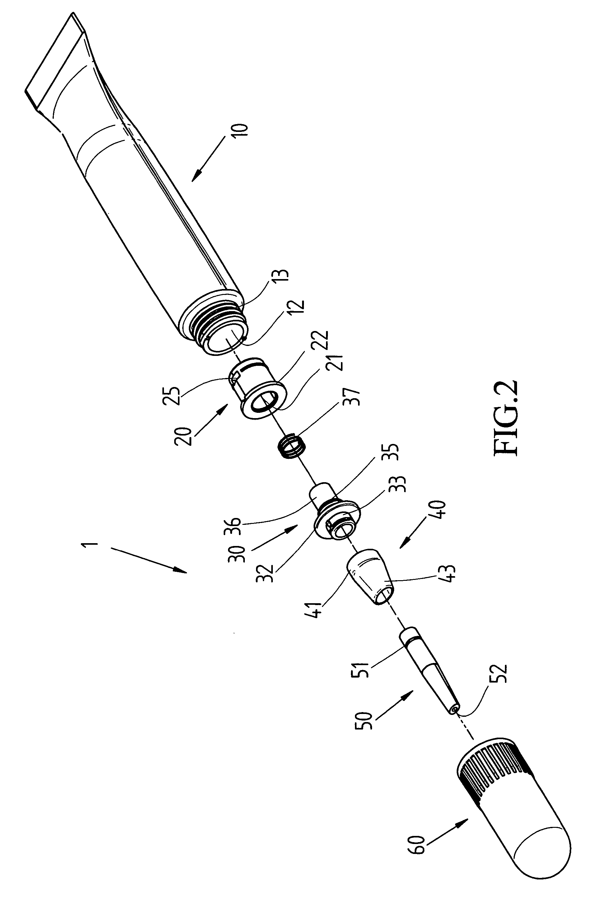
[0022]As shown in FIGS. 1–3, the invention is a tube style cosmetic container (1)

[0023]A tube (10), in which cosmetic liquid (11) is contained, includes an opening (12) arranged axially at one end. A threaded part (13) is arranged at the outskirt of the opening (12).

[0024]One end of an axle sleeve (20) is provided with a holding space (21). A resistant holding part (22) protrudes circularly at an end flange, and the resistant holding part (22) is sleeved at the end flange of the opening (12). In addition, a large diameter round hole (23) is concaved in the holding space (21), and first and second resistant holding surfaces (24) are respectively formed at ends of the round hole (23). At the other end of axle sleeve (20), a corresponding through material discharge hole (25) is formed at an appropriate place of the outskirt, and the material discharge hole (25) is connected to the cosmetic liquid (11) of the tube (10).

[0025]Inside of a hollow piston rod (30), a protruding part (31) is ...


PUM


Abstract

A tube style cosmetic container structure includes a tube having an opening arranged axially at one end. An axle sleeve is connected to the tube by being sleeved inside of the opening. A hollow piston rod includes a flanged disk arranged at the outside. A spring is placed against an end surface formed by a holding space of the axle sleeve and the hollow rod piston. A hollow sleeve pipe is firmly sleeved in the snatch part of the hollow piston rod. A hollow pencil pipe is sleeved by the hollow sleeve pipe and snatched by the protruding part of the hollow piston rod. An exterior cap can be screwed on the threaded part at the tube opening. When the exterior cap is screwed on, the material discharge hole can be wholly blocked, and no liquid will flow even if the tube is under certain pressure. When the exterior cap is screwed off and the tube is squeezed to force the contents out, no squeezed contents will backflow even if the pressure is reduced or stopped.

Description

BACKGROUND OF THE INVENTION[0001]1. Field of the Invention[0002]The present invention relates to a tube style cosmetic container structure and, more particularly, to a cosmetic container that can prevent liquid overflow when its enclosure cap is tightly screwed on, can prevent liquid backflow when its enclosure cap is screwed off for usage, and can not only isolate air pollution, but also ease squeezing by a user.[0003]2. Description of Related Art[0004]For a conventional cosmetic pencil, a user firstly uncaps it before dressing. Then cosmetic liquid is forced to flow out in the direction of the pencil head by holding the pencil rod by one hand, and turning the rotatable handle of the cosmetic pencil by another hand. Thereby, a dressing can be made. Therefore, the cosmetic pencil has to be used in a rotational way that complicates its application, and the cosmetic liquid might be polluted and quality degraded due to contacting air.[0005]According to above description, the known cosm...

Claims


Application Information

Patent Timeline
Patent Type & Authority Patents(United States)
IPC IPC(8): B43M11/06
CPCA45D34/04
Inventor ZHANG, JUN
Owner CHUEN CHERN
Why Eureka
Try Eureka