Switching apparatus with an actuating shaft
a technology of actuating shaft and switching mechanism, which is applied in the direction of contact mechanism, non-positive displacement fluid engine, liquid fuel engine components, etc., can solve the problems of high precision and inability to increase the precision of such switching mechanism, and achieve the effect of improving the level of resolution, ensuring the difference between two different switching positions, and ensuring the accuracy of switching
- Summary
- Abstract
- Description
- Claims
- Application Information
AI Technical Summary
Benefits of technology
Problems solved by technology
Method used
Image
Examples
second embodiment
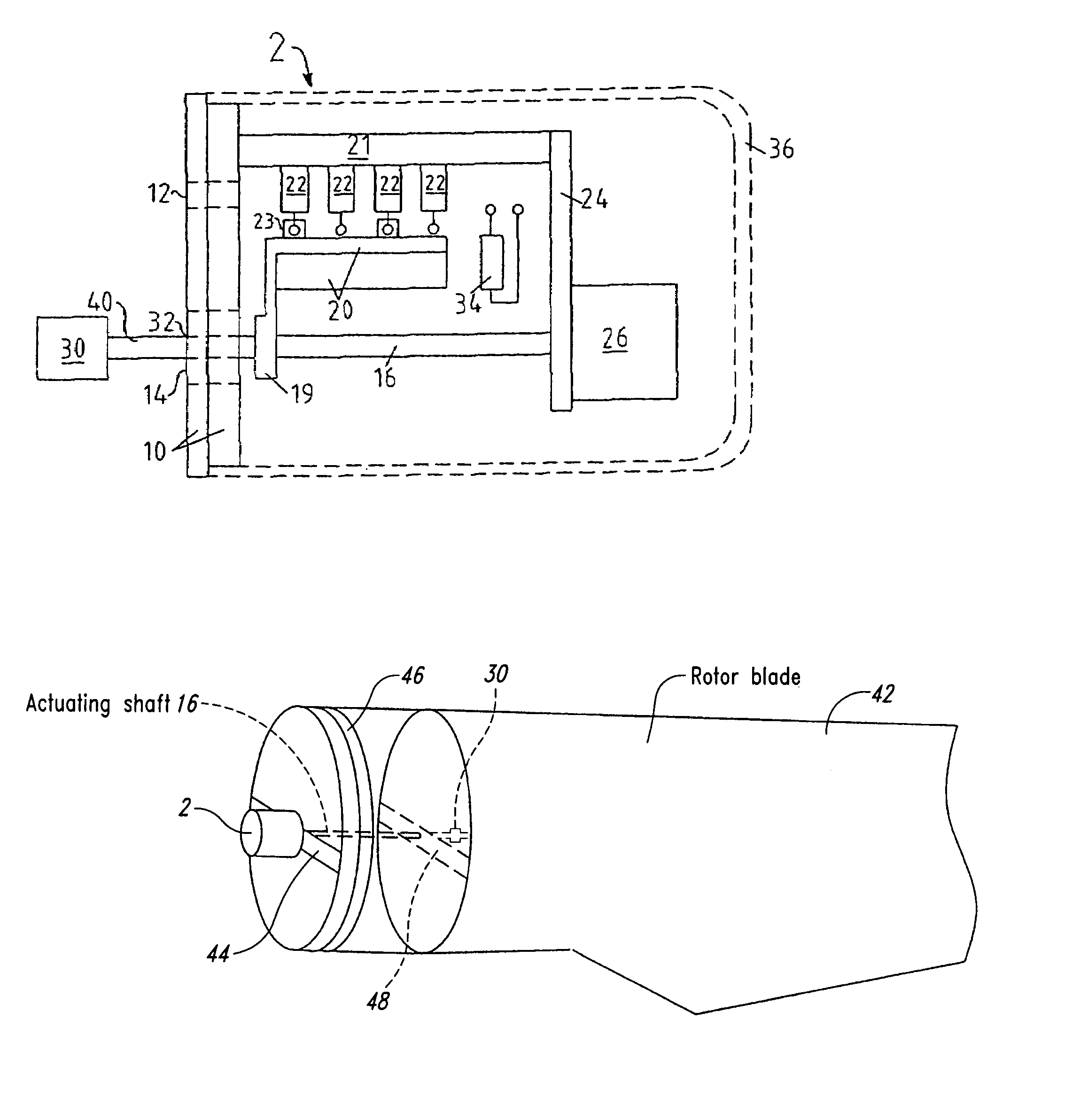
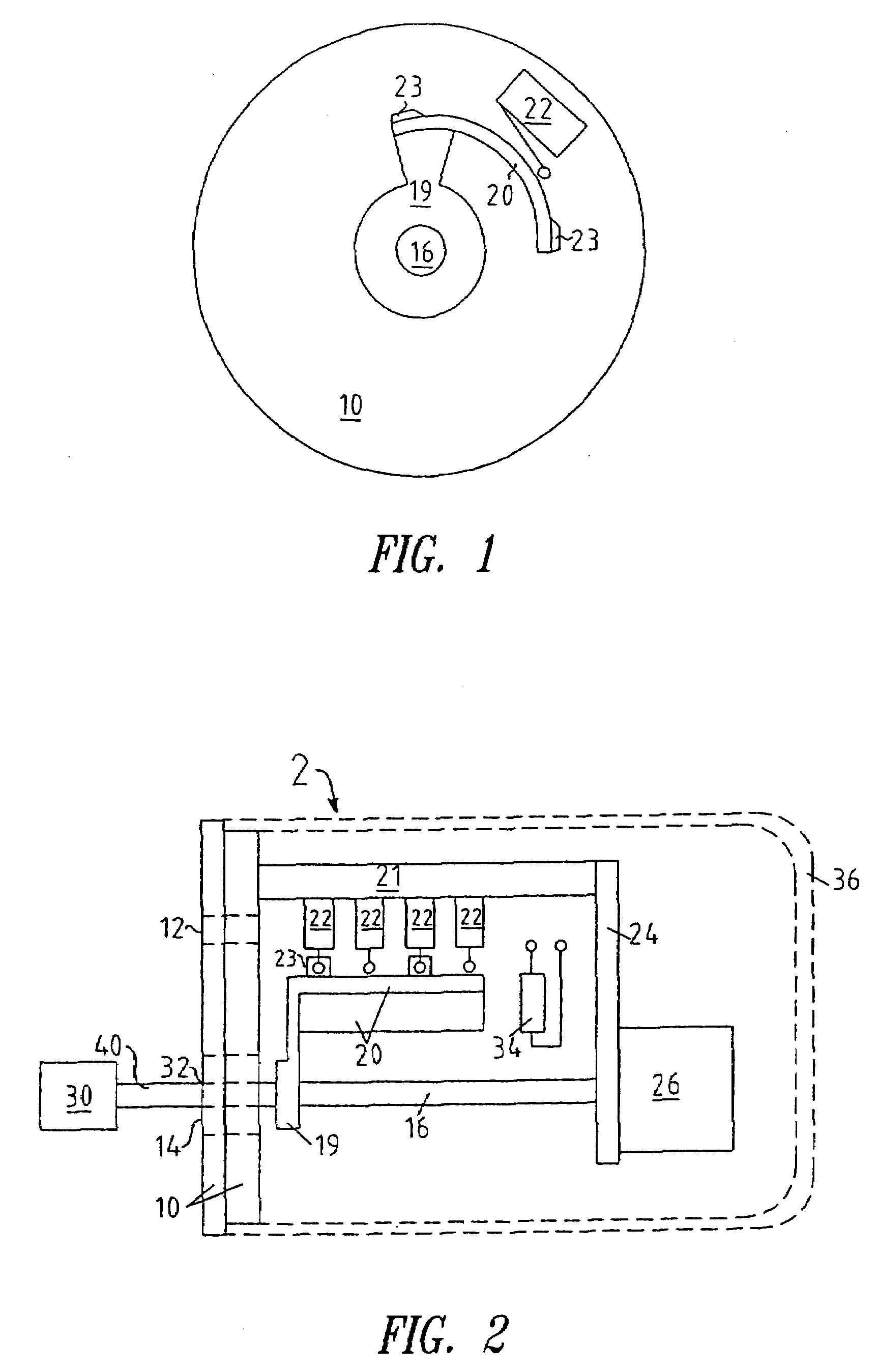
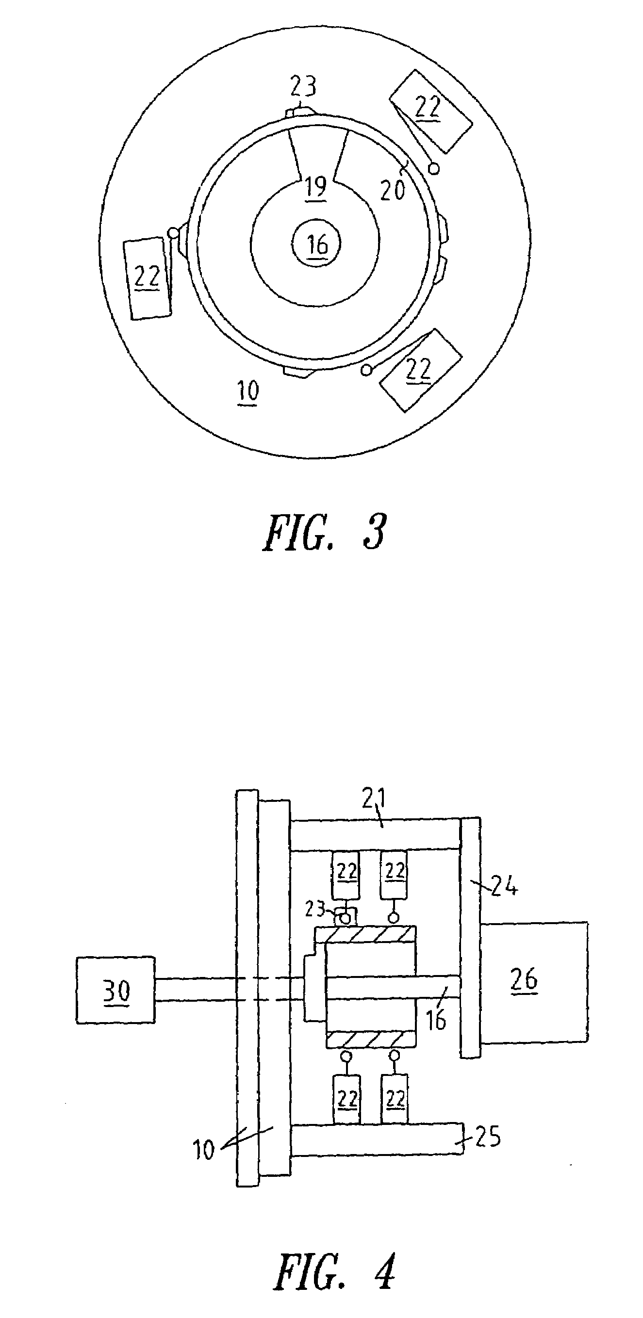
[0050]In this second embodiment, the essential difference is that the second actuating guide portion 20 extends completely around the actuating shaft 16. In this case, the plane of the area enclosed by the second actuating guide portion 20 extends radially with respect to the actuating shaft 16.
[0051]Switches 22 are arranged at uniform spacings over the outside periphery, in dependence on the intended maximum rotary angle of the switching apparatus. In the illustrated embodiment the rotary angle does not exceed 120° and thus three switches can be distributed over the periphery (see in particular FIG. 3). That arrangement therefore permits a more compact structure for a switching apparatus according to the invention. In this respect, FIG. 4 shows an arrangement having a third carrier plate 25 on which two switches 22 are arranged.
[0052]The respective switching time derives from the position of the raised cam portions 23. In the case of two switches 22 as shown in FIG. 3, there are tw...
fourth embodiment
[0054]FIG. 7 shows a side view of the switching apparatus according to the invention. In this case, instead of fork-type light barrier arrangements, reflection couplers are used as the switches 22 in order once again to produce corresponding signals by optical means. In order to avoid the switches 22 influencing each other in the case of a cam dip, the switches are arranged in two planes but in displaced relationship with each other, in such a way that no two switches 22 are disposed in opposite relationship. In that way, a suitable choice of the positions of the raised cam portions and the cam dips makes the structure of a switching apparatus according to the invention even more compact.
[0055]The mode of operation of a reflection coupler as a switch 22 differs in that respect from the mode of operation of a fork-type light barrier arrangement. In the case of the fork-type light barrier arrangement, the transmitter and the receiver are disposed separately in the mutually oppositely ...
PUM
 Abstract
Description
Claims
Application Information
 - R&D
- Intellectual Property
- Life Sciences
- Materials
- Tech Scout
- Unparalleled Data Quality
- Higher Quality Content
- 60% Fewer Hallucinations
Browse by: Latest US Patents, China's latest patents, Technical Efficacy Thesaurus, Application Domain, Technology Topic, Popular Technical Reports.
© 2025 PatSnap. All rights reserved.Legal|Privacy policy|Modern Slavery Act Transparency Statement|Sitemap|About US| Contact US: help@patsnap.com


