Metatarsophalangeal resurfacing joint

a metal resurfacing and metatarsal joint technology, applied in the field of implants, can solve the problems of inability to achieve maximum stability of implants and incorrect anatomical positions, and achieve the effects of optimizing the fixation of implants to the bone, optimizing the fixation of implants, and increasing the stability of implants

Inactive Publication Date: 2007-02-13
HOWMEDICA OSTEONICS CORP
View PDF5 Cites 28 Cited by
  • Summary
  • Abstract
  • Description
  • Claims
  • Application Information

AI Technical Summary

Benefits of technology

[0018]The present metatarsophalangeal implant enjoys a number of advantages and improvements over the prior art. For instance, the stability of the implant has been increased by anatomically shaping the stem to the intramedulary canal of the proximal phalanx. An anatomically shaped stem conforms to the endosteal cortex in the shaft, and hence maximizes the stability and optimizes the fixation of the implant to the bone. The bearing surface of the implant is angulated to align with the articulating surface of the proximal phalanx to maintain proper biomechanics with the joint. The base plate is positioned at an anatomical angle with the stem following the anatomic angular relation between the shaft and the proximal base of the proximal phalanx, which further increases the stability of the implant secured in the bone. The stem is surface treated to further improve the adhesion of the stem to the intramedulary canal of a bone.
[0019]In a preferred embodiment, the surface of the stem of the implant of the present invention may be knurled by cross-hatching or checking, to provide an effective gripping surface. The surface may be provided with a combination of checked and grooved areas, to further enhance grip in the intramedulary canal.

Problems solved by technology

This is anatomically incorrect when the implant is inserted into the bone.
As the result, the maximum stability of the implant can not be achieved.

Method used


Image

  • Metatarsophalangeal resurfacing joint
  • Metatarsophalangeal resurfacing joint
  • Metatarsophalangeal resurfacing joint

Examples


Embodiment Construction

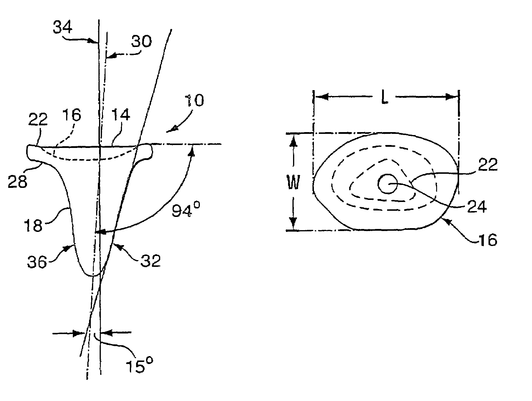
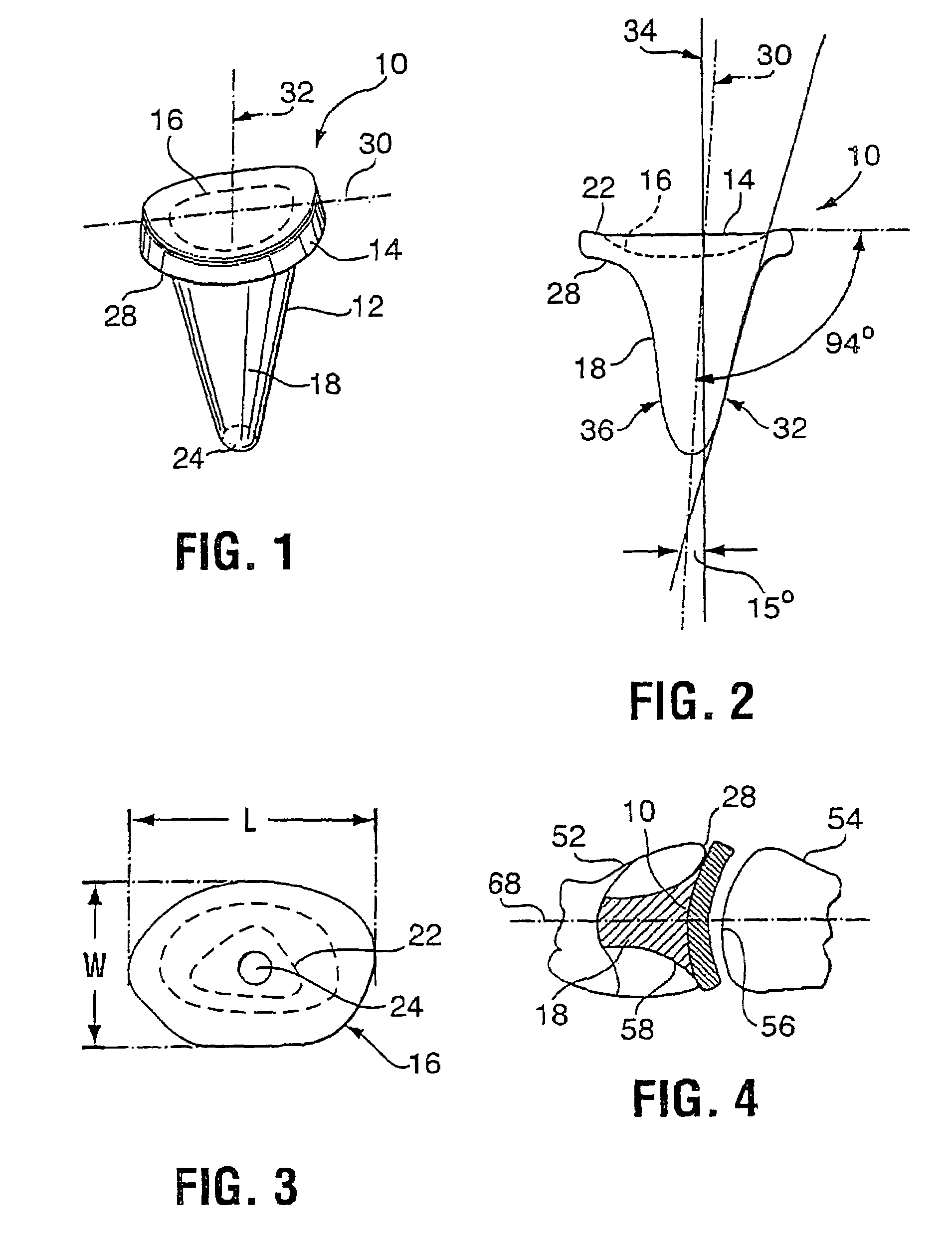
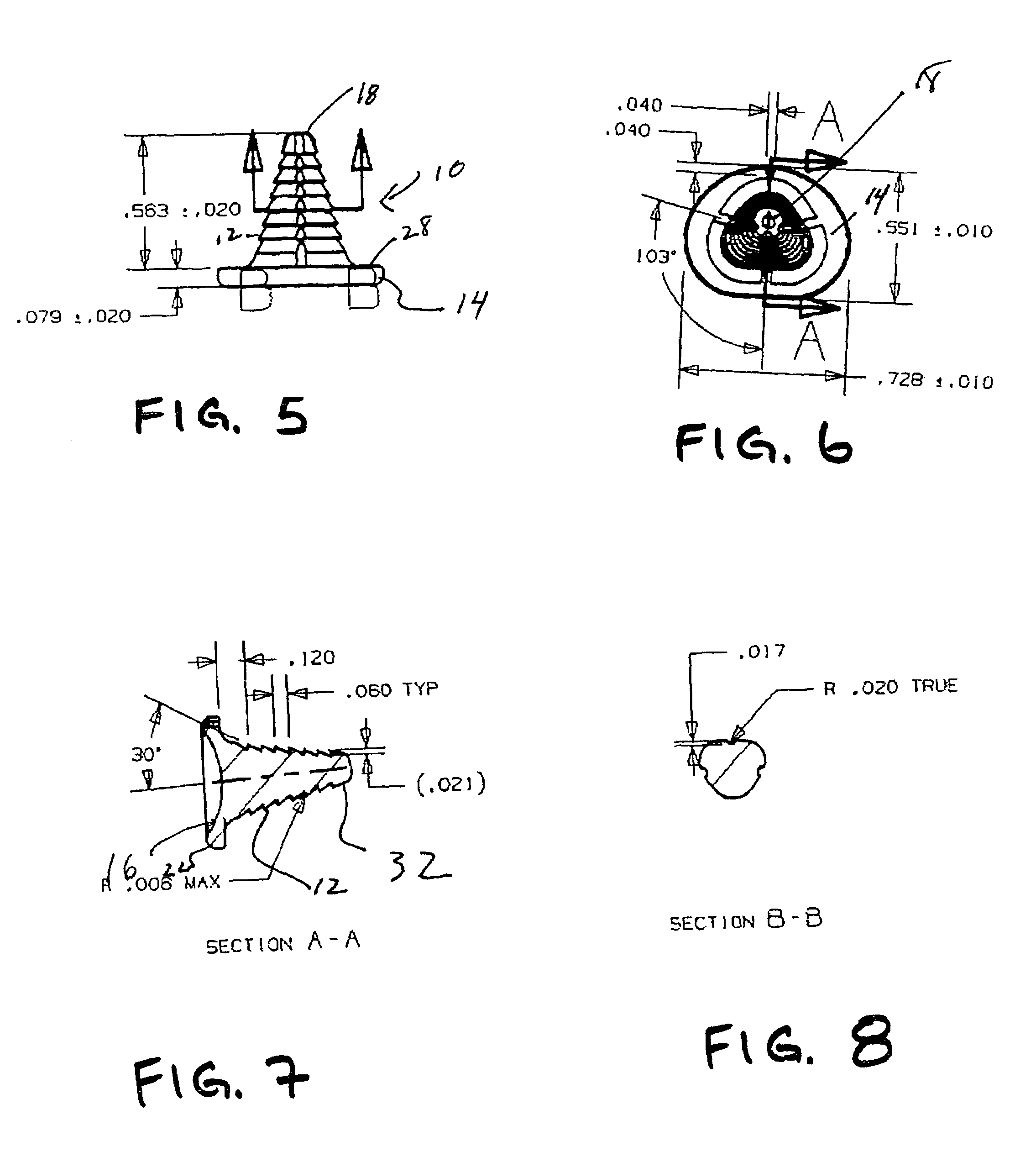
[0034]Referring to FIG. 1, a great toe implant 10 has a base plate 14 coupled to an elongated stem 18, which is adapted to be inserted in the intramedulary canal of a proximal phalanx. The base plate is ovoid shaped, having a substantially concave bearing surface 16 that is intended to contact and articulate with the head of the first metatarsal in the great toe joint, and a flat rear surface 28 opposite the concave bearing surface. A stem 18 projects from the rear surface 28 of the base plate away from the concave bearing surface 16 at an angle. The stem 18 is anatomically shaped to an intramedulary canal of a proximal phalanx. As illustrated in the top plan view of the stem in FIG. 2, the stem 18 has a general triangular gibbous shape 22, with the extent of the angular gibbosity decreasing as the stem is further away from the base plate 14 whereby the bottom 18 of the stem is almost shaped in a circle. In the preferred embodiments illustrated in FIGS. 5 to 12, the triangularity is...


PUM

PropertyMeasurementUnit
anatomical angleaaaaaaaaaa
angleaaaaaaaaaa
angleaaaaaaaaaa

Abstract

The present invention provides a prosthesis for implantation at the proximal articular surface of a proximal phalange, of a human great toe. The prosthesis comprises a base portion having a generally concave bearing surface shaped to articulate with the distal articular surface of a metatarsal bone, and a flat surface opposite the bearing surface for emplacement against a resected surface of the proximal phalange of the great toe of the human subject. A stem extends distally from the flat surface of the base portion, for implantation in the intramedulary canal of a proximal phalange of the great toe of the human subject. The stem has a generally frustoconical shape, with a substantially oval wide end at the flat surface of the base portion, tapering to a substantially circular end. The generally frustoconically shaped stem has a longitudinal axis that is inclined at an anatomical angle, of about 94° to the base portion, to align with the intramedulary canal of a proximal phalanx of the great toe of the human subject.

Description

[0001]This is a Continuation-in-Part application of U.S. application Ser. No. 09 / 997,343 filed Nov. 29, 2001 now abandoned.FIELD OF THE INVENTION[0002]The invention relates to an implant that resurfaces a bone, in particular the proximal phalanx of the great toe in the metatarsophalangeal.BACKGROUND OF THE INVENTION[0003]Great toe implant devices have been used to replace the defective natural metatarsophalangeal (MTP) joints. Hemi-joint replacement is generally preferred to full joint replacement when the proximal phalanx in the great toe still has good bone stock and the first metatarsal has an integral head. The implants are used to remove pain in the first metatarsal joint incurred from inflammatory arthritis and to restore joint kinetics by replacing the damaged base portion of the proximal phalanx.[0004]U.S. Pat. No. 5,326,366 to Pascerella et. al. discloses an implant device which has an elliptical base with a concave bearing surface that has an anafomically shaped proximal a...

Claims


Application Information

Patent Timeline
Patent Type & Authority Patents(United States)
IPC IPC(8): A61F2/42A61F2/00A61F2/30
CPCA61F2/4225A61F2002/30205A61F2002/30654A61F2002/30685A61F2002/30827A61F2310/00796A61F2002/30841A61F2002/30904A61F2002/4235A61F2230/0067A61F2310/00029A61F2002/30836A61F2002/4233
Inventor SAUNDERS, GERALD ANTHONY BRIDENSORBIE, CHARLES
Owner HOWMEDICA OSTEONICS CORP
Why Eureka
Try Eureka