Continuous process for the alkylation of hydrocarbons

a technology of hydrocarbons and alkylation process, which is applied in the direction of hydrocarbon preparation catalysts, organic chemistry, chemistry apparatus and processes, etc., can solve the problems of reactor flushing, valve and tubing clogging, and reactors need to be introduced in separate apparatuses

Active Publication Date: 2007-02-13
ALBEMARLE NETHERLANDS BV
View PDF6 Cites 61 Cited by
  • Summary
  • Abstract
  • Description
  • Claims
  • Application Information

AI Technical Summary

Problems solved by technology

Such a process requires a lot of valves and tubing.
A second disadvantage of this process is the need for the introduction into the apparatus of two separate isobutane-containing streams: a feed stream and a regenerant stream.
A third disadvantage is that before cycling a reactor from the regeneration to the alkylation zone and vice versa, the reactor needs to be flushed.

Method used


Image

  • Continuous process for the alkylation of hydrocarbons
  • Continuous process for the alkylation of hydrocarbons

Examples


first embodiment

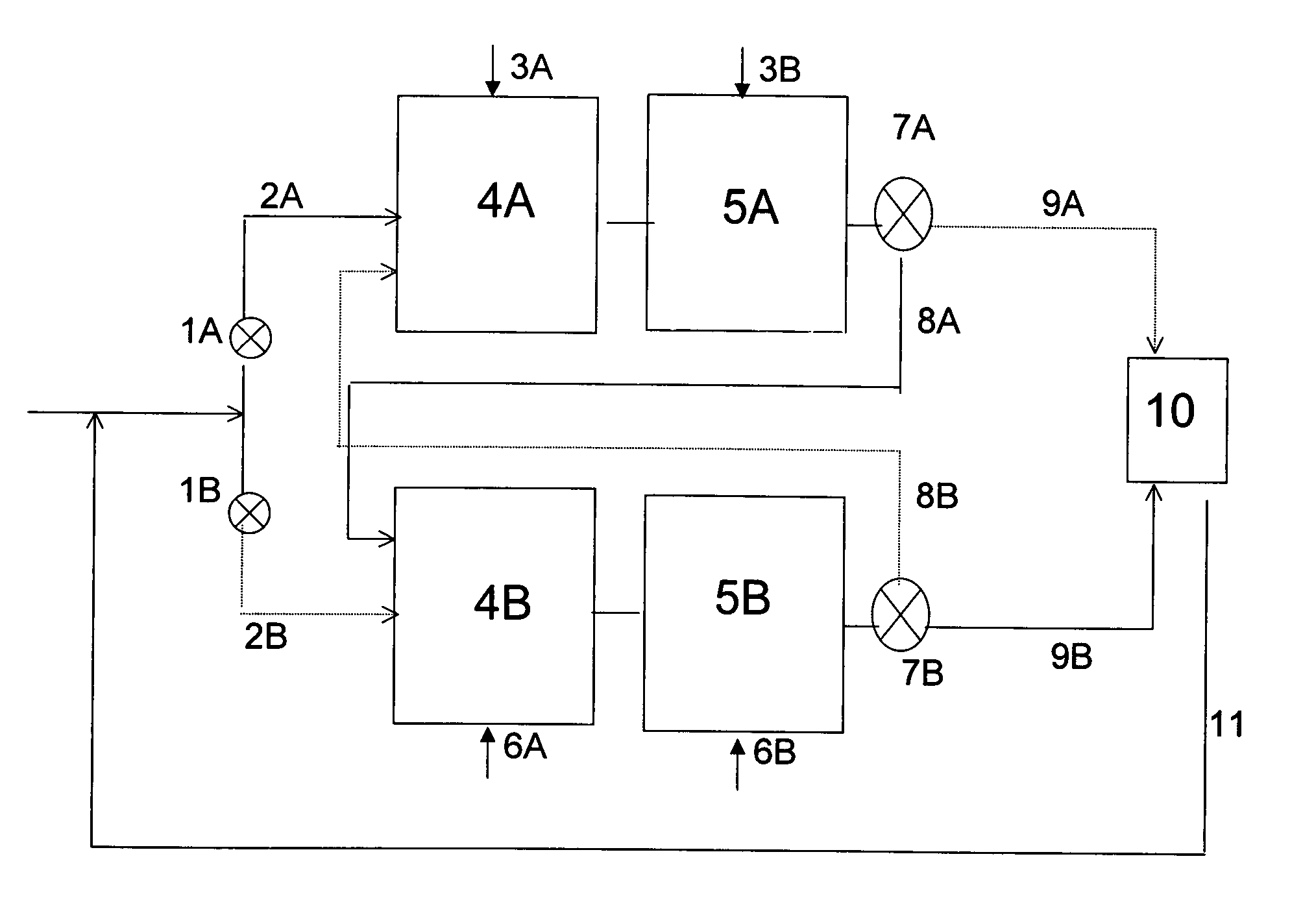
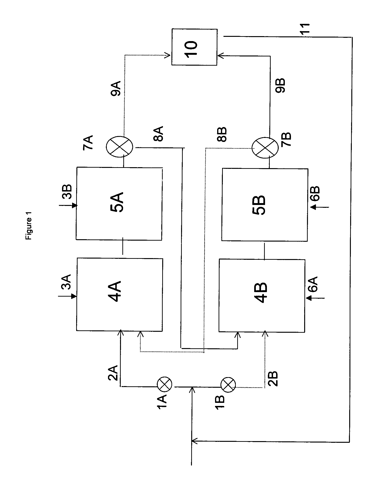
[0027]In the present invention, at least a portion of the alkylation mode alkylate-containing effluent is led via valve system 7A and through duct 8A to zone B, which contains reactors 4B and 5B, which reactors are in the regeneration mode. If only a portion of the alkylation mode alkylate-containing effluent is led to zone B, the remaining portion of the alkylation mode alkylate-containing effluent can be led through duct 9A to separation unit 10. If desired, alkylatable compound may be added to the portion of the alkylation mode alkylate-containing effluent which is led to zone B. In this embodiment it is preferred, however, to lead the entire alkylation mode alkylate-containing effluent to zone B.

[0028]Hydrogen is fed to reactor 4B or to both reactor 4B and reactor 5B through inlet 6A and inlets 6A and 6B, respectively. The alkylation mode alkylate-containing effluent which is led to zone B is first introduced into reactor 4B. Subsequently, the effluent of reactor 4B, which is a ...

second embodiment

[0031]In a second embodiment, the entire alkylation mode alkylate-containing effluent is led through duct 9A to separation unit 10. At the same time, alkylatable compound is introduced via duct 2B into reactor 4B, which is in the regeneration mode. The effluent of this reactor is subsequently led to reactor 5B. The effluent of reactor 5B, i.e. the regeneration mode effluent, is then led via valve system 7B and through duct 9B to separation unit 10. The reactors in zone A and zone B can be cycled between the alkylation mode and the regeneration mode by switching the streams coming through inlets 3A / B and 6A / B. By switching the streams coming through inlets 3A / B and 6A / B hydrogen is fed to reactor 4A or to reactors 4A and 5A both and the alkylation agent is fed to reactors 4B and 5B.

third embodiment

[0032]In a third embodiment, no streams are introduced into reactor 4B via ducts 2B or 8A while reactors 4B and 5B are operating in the regeneration mode, and the entire alkylation mode alkylate-containing effluent is led through duct 9A to separation unit 10. Alkylate, formed during the time when reactors 4B and 5B operated in the alkylation mode, is still present in these reactors. In principle, reactors 4B and 5B will be isolated from the system, meaning that no streams leave the reactor via valve system 7B during the regeneration period. However, it may be necessary to relieve the pressure from the reactor, e.g. via duct 9B.

[0033]The reactors in zone A and zone B can be cycled between the alkylation mode and the regeneration mode by, e.g., (i) switching the streams coming through inlets 3A / B and 6A / B and (ii) changing the streams through ducts 2A and 2B. In this mode, hydrogen is fed to reactor 4A or to reactors 4A and 5A both and the alkylation agent is fed to reactors 4B and 5...


PUM

PropertyMeasurementUnit
temperatureaaaaaaaaaa
pressureaaaaaaaaaa

Abstract

A continuous alkylation process performed in an apparatus comprising a series of at least two zone A reactors and a series of at least two zone B reactors, in which the zone A reactors and the zone B reactors cycle between alkylation mode and mild regeneration mode, and wherein the alkylation mode comprises introducing an alkylation agent into a first reactor of the zone through which the alkylatable compound passes, reacting a portion of the alkylatable compound with a portion of the alkylation agent to produce a product stream, and performing this operation at least once more in a downstream reactor in the same zone employing, instead of alkylatable compound, a stream comprising the product stream.

Description

CROSS REFERENCE TO RELATED APPLICATION[0001]This application claims priority from European Patent Application No. EP 01202206.7, filed Jun. 8, 2001.BACKGROUND OF THE INVENTION[0002]1. Field of the Invention[0003]This invention relates to a continuous process for the alkylation of hydrocarbons over a solid acid catalyst, and more in particular a process in which the catalyst is also regenerated.[0004]2. Prior Art[0005]Within the framework of the present invention, the term alkylation refers to the reaction of an alkylatable compound, such as an aromatic or a saturated hydrocarbon, with an alkylation agent, such as an olefin. Without limiting its scope, we will further illustrate the invention by discussing the alkylation of saturated hydrocarbons, in general branched saturated hydrocarbons, with an olefin to give highly branched saturated hydrocarbons with a higher molecular weight.[0006]U.S. Pat. No. 5,523,503 discloses the alkylation of hydrocarbons, i.e. isobutane, in an apparatus...

Claims


Application Information

Patent Timeline
Patent Type & Authority Patents(United States)
IPC IPC(8): C07C2/64C07C2/54C07B37/04C07B37/02C07B61/00C07C2/58C07C9/16
CPCC07C2/58C07C2523/44C07C2523/42Y02P20/584
Inventor VAN BROEKHOVEN, EMANUEL HERMANUSSONNEMANS, JOHANNES WILHELMUS MARIAZUIJDENDORP, STEPHAN
Owner ALBEMARLE NETHERLANDS BV
Why Eureka
Try Eureka