Hanger bracket

a technology of hanging brackets and fire blocks, which is applied in the direction of rod connections, nails, mechanical equipment, etc., can solve the problems of time-consuming and often wasteful process, inability to use, and the time and energy required to nail each fire block onto the studs

Active Publication Date: 2007-02-20
ROBBINS ENG
View PDF8 Cites 55 Cited by
  • Summary
  • Abstract
  • Description
  • Claims
  • Application Information

AI Technical Summary

Benefits of technology

[0003]To overcome these disadvantages it is desirable to have a structure that not only provides for a quick and relatively unskilled installation of the fire blocks, but also compensates for minor variations in the spacing between adjacent studs, so that slightly undersized fire block boards can be used effectively.

Problems solved by technology

This is a time-consuming and often wasteful process in that adjacent studs may either be bowed or for other reasons not spaced identically from the adjacent stud.
If the board is inadvertently cut too short, it cannot be used because it would not provide the desired blockage to prevent spread of a fire.
Moreover, having to nail each fire block onto the studs takes a significant amount of time and energy.

Method used


Image

  • Hanger bracket
  • Hanger bracket
  • Hanger bracket

Examples


Embodiment Construction

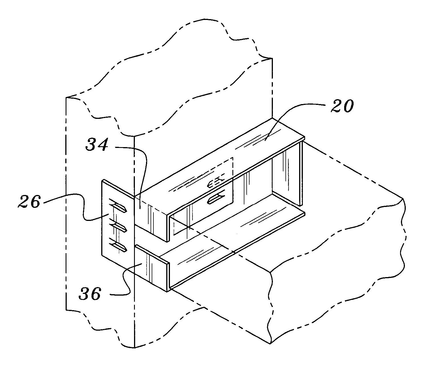
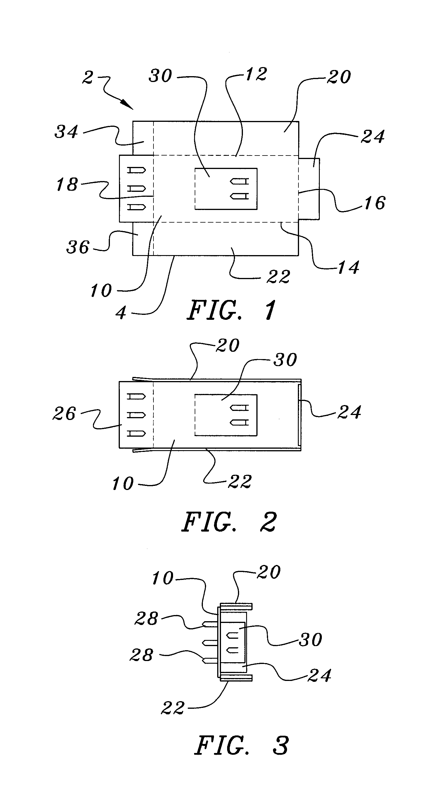
[0013]A preferred embodiment of the bracket 2 of this invention is illustrated in the drawings FIGS. 1–9. This bracket is suitably formed of a piece of stiff sheet material, suitably sheet steel, and preferably is formed by stamping and folding various components. FIG. 1 is a planar view of a blank 4 of stiff sheet material from which the bracket of this invention is stamped. In this illustration the cut lines are shown as solid lines and the fold lines are shown as dashed lines, with the combination of cut lines and fold lines defining a plurality of panels.

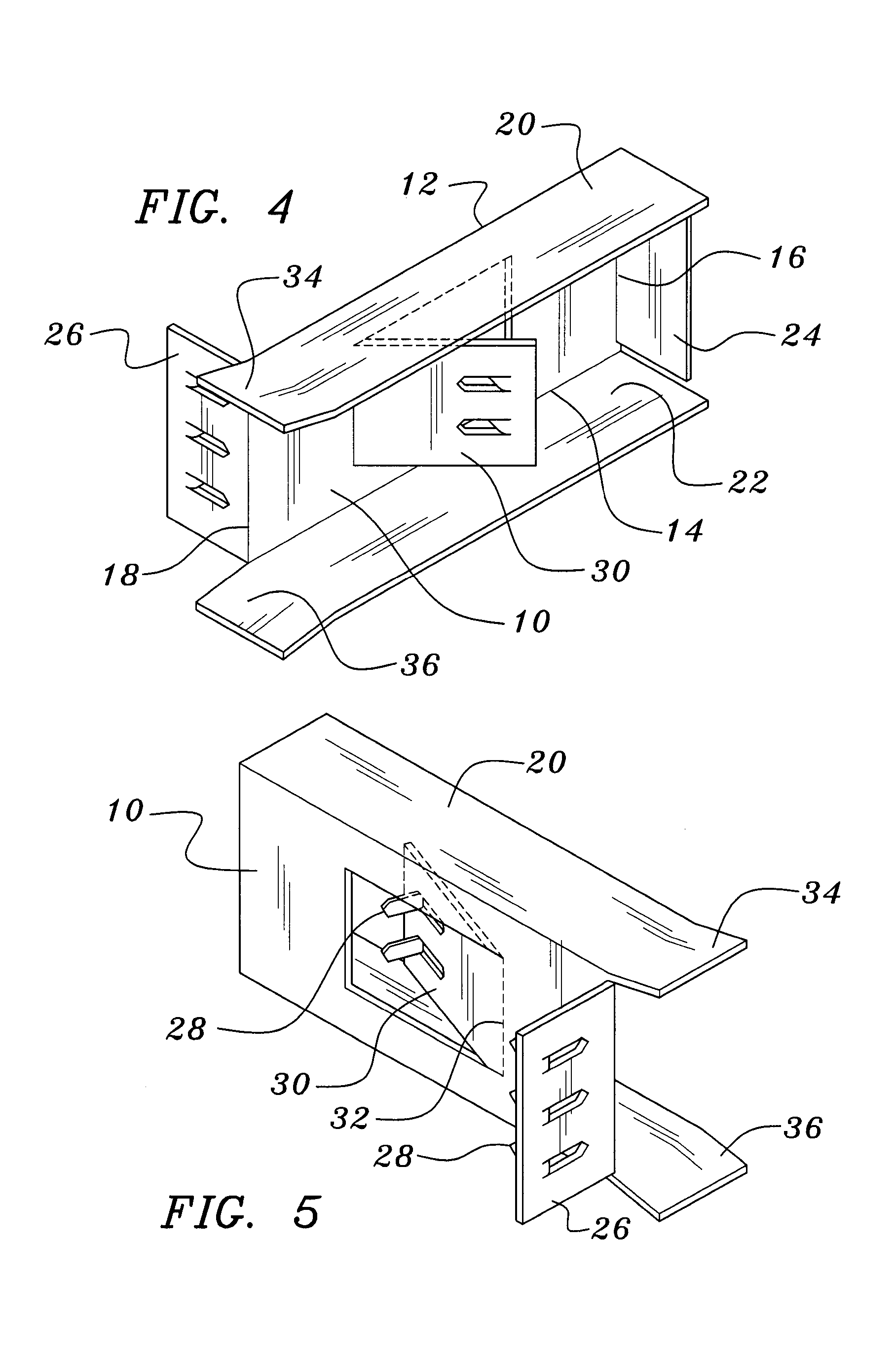
[0014]In FIG. 1, the bracket comprises a generally rectangular and substantially planar base panel 10 having opposed and generally parallel first and second edges 12 and 14, and opposed and generally parallel third and fourth edges 16 and 18. As shown in FIG. 2 and subsequent figures, folding the edge portions along fold lines 12 and 14 forms a pair of generally opposed and substantially parallel panels 20 and 22 extending gener...


PUM


Abstract

A bracket is provided comprising a rectangular and substantially planar base panel, a pair of generally opposed and substantially parallel panels extending generally normal to the base panel and spaced apart, with a third panel extending generally normal to the base panel along a third edge, with a fourth panel extending generally normal to the base panel along a fourth edge thereof, with that fourth panel extending in a direction generally opposite the direction of the first, second and third panels, whereby the first, second and third panels form a channel along the base panel and having one closed end. A method of use of this bracket is also disclosed.

Description

BACKGROUND OF THE INVENTION[0001]This invention relates to construction brackets, and more particularly to a bracket for supporting a horizontal board or beam, such as the type that may serve as a fire block between vertical studs in the wall of the structure, and a method for installing that bracket.[0002]A fire block is well known in the construction industry as a board or beam set between two studs to inhibit the spread of fire by limiting the oxygen available to the fire and by reducing the “chimney effect” of the space between vertical studs. Traditionally, the installation of a fire block includes delivery of appropriately-sized boards or beams, conventionally 2×4 boards, to the construction area and then cutting the boards or beams to the appropriate length and sizing them to the exact distance between each pair of studs, and finally nailing the boards or beams in place. This is a time-consuming and often wasteful process in that adjacent studs may either be bowed or for othe...

Claims


Application Information

Patent Timeline
Patent Type & Authority Patents(United States)
IPC IPC(8): E04B7/04E04B1/38E04C5/00
CPCF16B15/0046E04B1/2608E04C2003/026F16B7/0486
Inventor PETROVA, GEORGE I.
Owner ROBBINS ENG
Why Eureka
Try Eureka