Wrapping apparatus comprising a dispenser for dispensing stretched wrap film

a technology of wrapping apparatus and dispenser, which is applied in the direction of packaging goods, bundling articles, transportation and packaging, etc., can solve the problems of time-consuming and laborious, difficult film threading, and even worse problems, and achieve the effect of convenient and ergonomic film roll exchange and facilitate film roll exchang

Active Publication Date: 2007-02-20
M HALOILA
View PDF10 Cites 55 Cited by
  • Summary
  • Abstract
  • Description
  • Claims
  • Application Information

AI Technical Summary

Benefits of technology

[0006]Accordingly, it is an object of the present invention to provide a new and improved wrapping apparatus having a film dispenser which enables an easy and ergonomic film roll exchange and film threading between the guide and prestretch rollers of the film dispenser.
[0008]The foregoing and other objects are achieved in accordance with the teachings of the present invention through the provision of a new and improved wrapping apparatus which comprises a dispenser for dispensing stretched wrap film, the film having a first side and a second side, the dispenser including a first frame assembly having a first base member; a second frame assembly having a second base member mounted to the first base member by a hinge having a substantially horizontal hinge axis, the second frame assembly being able to be tilted around the hinge axis; a film roll spindle for rotatably holding a film roll in the dispenser in a substantially vertical position, the spindle being mounted in the second frame assembly; upstream and downstream prestretch rollers for engaging the first side of the film, the upstream and downstream prestretch rollers being mounted in the first frame assembly; guide rollers for engaging the second side of the film in the near proximity of the upstream and downstream prestretch rollers for deflecting and guiding the film to form a tortuous path around the guide and prestretch rollers, the guide rollers being mounted in the second frame assembly. The second frame assembly is movable between a closed position and an open position. In the closed position the second frame assembly is in a position in which the film roll spindle and the guide rollers are parallel with respect to the prestretch rollers. In the open position the film roll spindle and guide rollers are tilted to an angle with respect to the prestretch rollers in order to enable film threading to an upwardly opening gap formed between the prestretch rollers and the guide rollers and to facilitate exchange of the film rolls.
[0010]The invention has the advantage that the exchange of the film roll is made very easy as the second frame assembly is pivotally moved from its closed position to its open position such that the film roll spindle is moved from its vertical orientation and tilted outwardly so as to be easily accessible for the operator. Simultaneously with this pivotal movement of the second frame assembly, an upwardly open gap is formed between the prestretch rollers and the guide rollers and is readily accessible from above for film threading.

Problems solved by technology

A problem arises in the situation when it is necessary to exchange or replace the film roll.
In the prior art dispenser this is very time consuming and laborious, because the film roll holder always preserves its vertical orientation in the first frame assembly being stationary in the film dispenser.
Further, film threading is difficult because the operator must insert his hand and fingers inside the dispenser in order to pull the film from the film roll located behind the prestretch rollers to the front side of the prestretch rollers.
Further, this problem becomes even worse in a wrapping apparatus of turntable type wherein it is desirable to encapsulate the film dispenser inside the inner space of the vertical box-like column wherein the dispenser is guided for vertical movement.

Method used


Image

  • Wrapping apparatus comprising a dispenser for dispensing stretched wrap film
  • Wrapping apparatus comprising a dispenser for dispensing stretched wrap film
  • Wrapping apparatus comprising a dispenser for dispensing stretched wrap film

Examples


Embodiment Construction

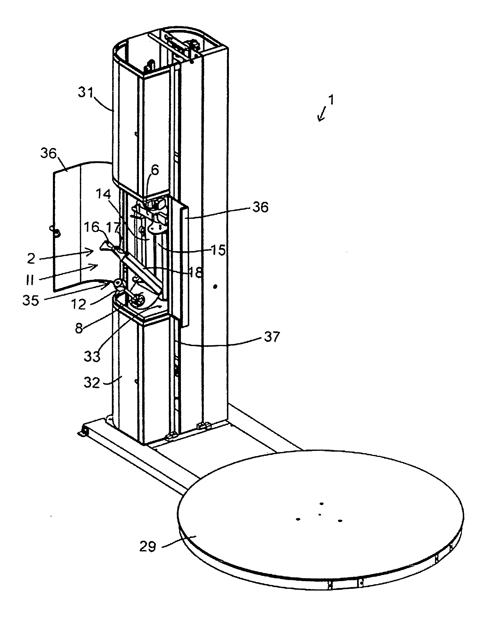
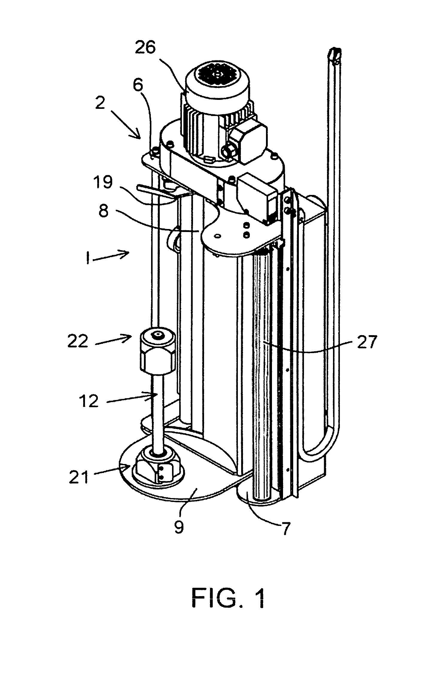
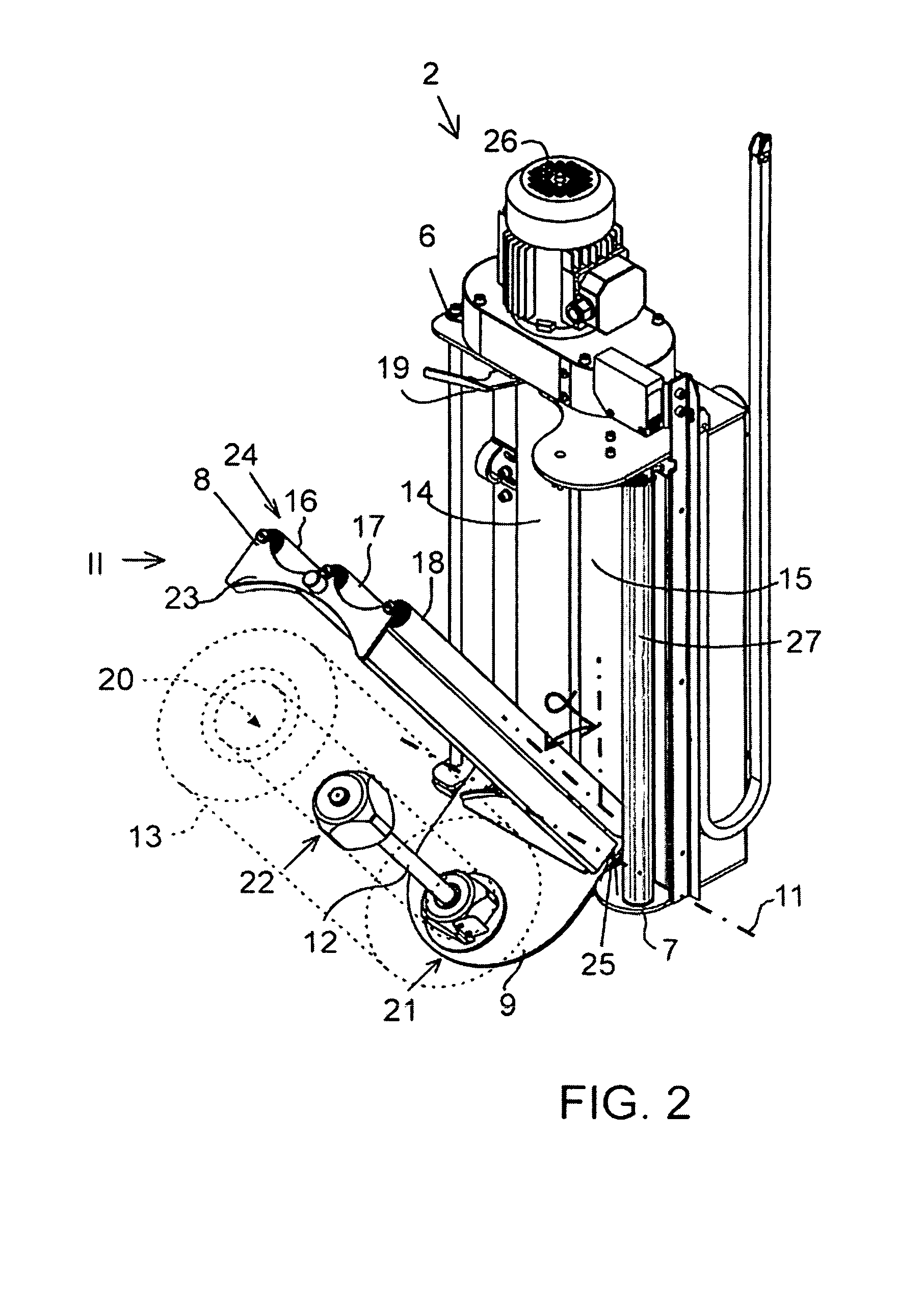
[0029]FIGS. 1 to 3 show a film dispenser 2 which is provided for dispensing stretched wrap plastic film (not shown) in a wrapping apparatus.

[0030]As can be seen from FIGS. 1, 2 and 3 the dispenser 2 includes a first frame assembly 6 having a first base member 7 and a second frame assembly 8 having a second base member 9. The second base member 9 is pivotally mounted to first base member 7 by a hinge 10 (in FIG. 3). The hinge 10 has a substantially horizontal hinge axis 11. The second frame assembly 8 can be tilted around the hinge axis 11 between a closed position I shown in FIG. 1 and an open position II shown in FIG. 2.

[0031]Further, the dispenser 2 comprises a film roll spindle 12 which is adapted to hold a film roll 13 in the dispenser 2 in a substantially vertical position when it is ready for operation in the closed position I. In FIG. 2 the film roll 13 is schematically drawn with broken lines. The spindle 12 allows free rotation of the film roll 13. The spindle 12 is mounted...


PUM

PropertyMeasurementUnit
angleaaaaaaaaaa
angleaaaaaaaaaa
tensionaaaaaaaaaa

Abstract

Wrapping apparatus comprises a dispenser, for dispensing stretched wrap film, which includes a first frame assembly, and a second frame assembly pivotally mounted upon the first frame assembly between a first closed position and second open position. A film roll spindle is mounted upon the second frame assembly along with a plurality of guide rollers, while upstream and downstream prestretch rollers are mounted upon the first frame assembly. When the second frame assembly is disposed at the second open position, the film roll spindle and guide rollers project outwardly in a tilted orientation such that the exchange of film rolls, and the threading of the film between the guide rollers and the prestretch rollers, is facilitated.

Description

FIELD OF THE INVENTION[0001]The present invention relates to a wrapping apparatus comprising a dispenser for dispensing stretched wrap film for wrapping around a load.BACKGROUND OF THE INVENTION[0002]In prior art, specification U.S. Pat. No. 5,414,979 discloses a wrapping apparatus that includes a dispenser for dispensing stretched wrap film. The dispenser includes a first frame assembly and a second frame assembly. The second frame assembly is hinged to the first frame assembly so as to be able to be turned about a vertical hinge axis in relation to the first frame assembly. Further the dispenser includes a film roll holder for rotatably holding a film roll. The film roll holder is arranged in the first frame assembly in a substantially vertical position. In U.S. Pat. No. 5,414,979 the film roll holder is mounted in the first frame assembly. The dispenser also includes upstream and downstream prestretch rollers for engaging a first side of the film, which upstream and downstream pr...

Claims


Application Information

Patent Timeline
Patent Type & Authority Patents(United States)
IPC IPC(8): B65B11/04
CPCB65B41/12B65B11/045
Inventor KOSKELA, JANNE
Owner M HALOILA
Why Eureka
Try Eureka