Fuel system for a marine vessel with a gaseous purge fuel container

a fuel container and fuel system technology, applied in the field of fuel containers or fuel system modules, can solve problems such as excessive fuel consumption

Inactive Publication Date: 2007-02-20
BRUNSWICK CORPORATION
View PDF23 Cites 32 Cited by
  • Summary
  • Abstract
  • Description
  • Claims
  • Application Information

AI Technical Summary

Problems solved by technology

The system pumps an excessive amount of fuel through a plumbed fuel supply loop and cools recirculated fuel to cool all the components in the plumbed fuel supply loop.

Method used


Image

  • Fuel system for a marine vessel with a gaseous purge fuel container
  • Fuel system for a marine vessel with a gaseous purge fuel container
  • Fuel system for a marine vessel with a gaseous purge fuel container

Examples


Embodiment Construction

[0026]Throughout the description of the preferred embodiment of the present invention, like components will be identified by like reference numerals.

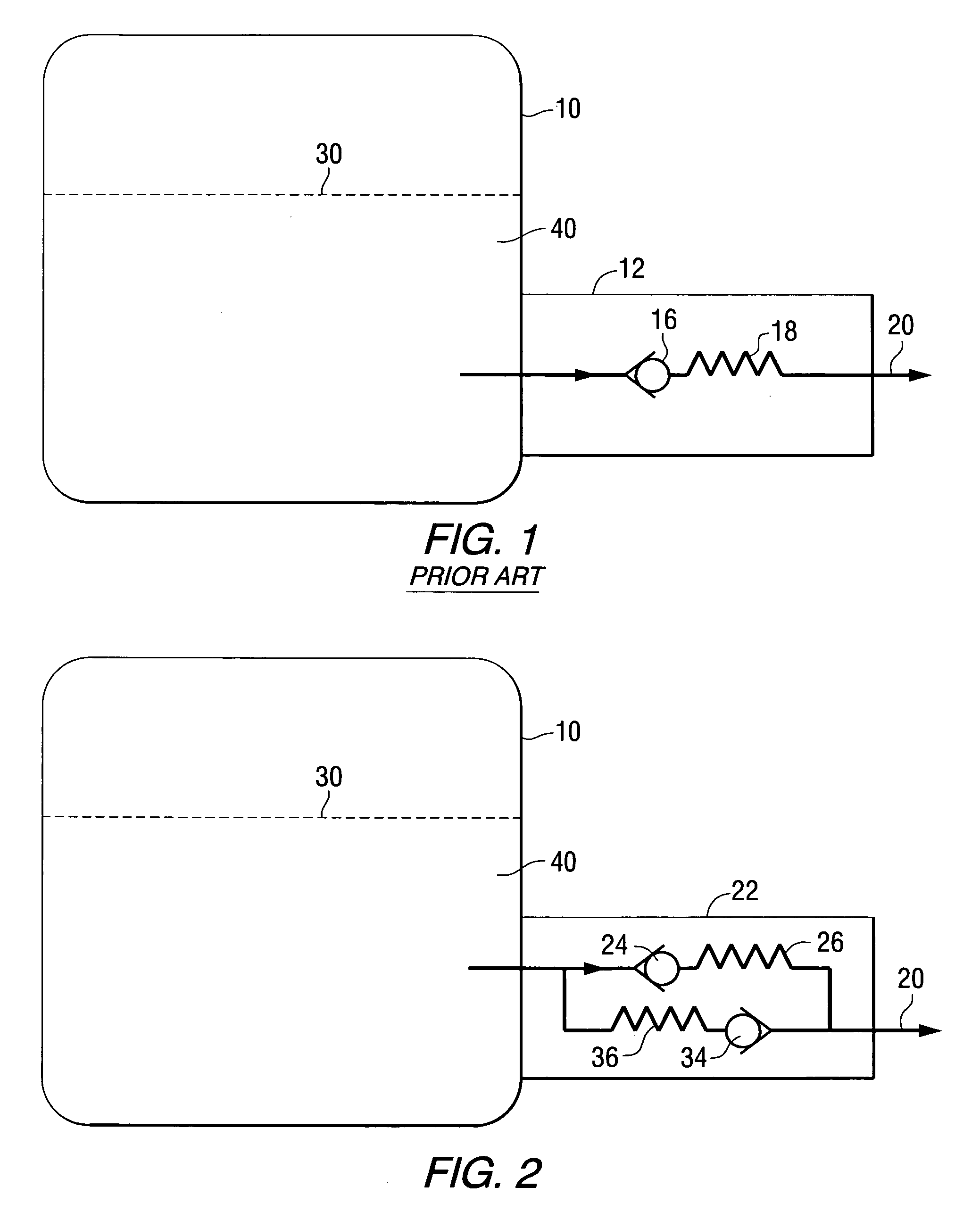
[0027]FIG. 1 shows a system that is generally known to those skilled in the art. A fuel reservoir 10 contains a fuel supply for a marine vessel. An outlet of the fuel reservoir 10 is provided with a valve 12 which operates as a check valve. The check valve 16 operates to permit flow of fuel from the reservoir 10 to an engine of a marine propulsion system in the direction represented by the arrow heads in FIG. 1. It blocks the flow of fuel in the opposite direction from the fuel supply system of a marine propulsion engine back toward the fuel reservoir 10. Depending on the force provided by a resilient member of the check valve 16, represented by reference numeral 18, the check valve 16 can also inhibit the flow from the reservoir 10 if the conduit 20 is severed between the fuel reservoir 10 and the marine engine.

[0028]FIG. 2 shows a fue...


PUM

PropertyMeasurementUnit
pressureaaaaaaaaaa
diameteraaaaaaaaaa
pressureaaaaaaaaaa

Abstract

A fuel container for a marine propulsion system is provided with a pump and a hose connected to an outlet of the pump and disposed within the cavity of the fuel container. The hose is provided with an opening, formed through its wall, through which a fluid can flow under certain circumstances. The opening is disposed in an ullage within the container and allows gaseous elements to be purged from the container when flow is induced from the container back to a fuel reservoir.

Description

BACKGROUND OF THE INVENTION[0001]1. Field of the Invention[0002]The present invention relates generally to a fuel system for a marine vessel and, more particularly, to a fuel container, or fuel system module, in which a hose is provided with an opening to purge gas from an ullage in the fuel container.[0003]2. Description of the Prior Art[0004]U.S. Pat. No. 4,732,131, which issued to Hensel on Mar. 22, 1988, discloses a fuel line purging device. A fuel injection system is provided with a purging device for purging gas, including air and vapor, from a fuel system. The device includes a pressure responsive valve permitting gas to flow from an inlet connected to the high pressure fuel line to a vent outlet and blocking flow when gas has been purged from the system and fuel pressure rises.[0005]U.S. Pat. No. 4,848,283, which issued to Garms et al. on Jul. 18, 1989, discloses a marine engine with combination vapor return, crankcase pressure, and cooled fuel line conduit. A marine propuls...

Claims


Application Information

Patent Timeline
Patent Type & Authority Patents(United States)
IPC IPC(8): F02M37/20F02M37/10F04D9/00
CPCF02M37/20F02M37/10Y10T137/3084Y10T137/86035Y10T137/86139Y10T137/86187
Inventor MERTEN, BRIAN L.
Owner BRUNSWICK CORPORATION
Why Eureka
Try Eureka