AI technical title is built by Patsnap AI team. It summarizes the technical point description of the patent document.
a technology of propellers and related vehicles, which is applied in the direction of machines/engines, toys, transportation and packaging, etc., can solve the problems of difficult control, difficult control, and inability to control these aircraft in a stable horizontal position, so as to increase the centrifugal force and reduce the likelihood of user injury
Inactive Publication Date: 2007-02-20
REHCO LLC
View PDF6 Cites 42 Cited by
Summary
Abstract
Description
Claims
Application Information
AI Technical Summary
This helps you quickly interpret patents by identifying the three key elements:
Problems solved by technology
Method used
Benefits of technology
Benefits of technology
[0013]In addition thereto the flybars may include weighted ends to increase the centrifugal force created by the rotation thereof. The main propeller described above may be used in other propeller related vehicles since each exhibits a means for stabilizing the propeller in a single plane, or since the main propellers include safety rings or arcs that decrease the likelihood a user may be injured by a rotating propeller.
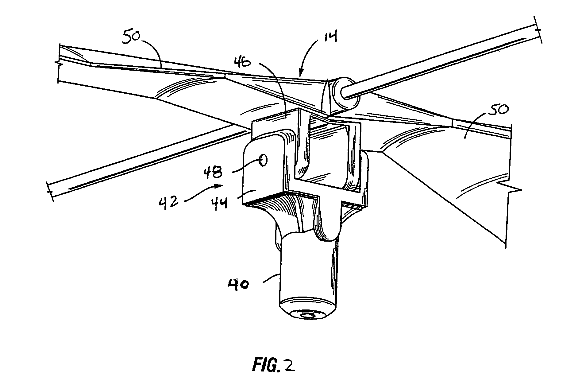
[0014]In another embodiment, the horizontal stabilizing means permits the main propeller to rotate and pivot about the main drive shaft independently from the airframe. However, when the main propeller is rotating and begins to pivot about the main drive shaft, the horizontal stabilizing means tends to return the main propeller in a substantially horizontal position.
Problems solved by technology
In general such aircraft, especially aircraft designed for the toy and hobby industry, require complex programming and mechanics to control the flight path and are especially difficult to control.
In most instances, controlling these aircraft to fly in a stable horizontal position takes countless hours of practice.
One problem that arises is when the propellers are rotating in the horizontal plane, variations such as wind or power fluctuations may cause the propeller blades to pitch further causing the aircraft to tip, turn, oscillate or bank.
However, as mentioned above these have a tendency to make the aircraft too expensive or too difficult to control, especially for children.
The ability to even maintain horizontal stability in these aircrafts is extremely difficult.
Oftentimes a child or user is injured when the user comes in contact with a rotating propeller.
Method used
Image
Click on the blue label to locate the original text in one second.
Reading with bidirectional positioning of images and text.
Examples
Embodiment Construction
[0028]While the invention is susceptible to embodiments in many different forms, there are shown in the drawings and will be described herein, in detail, the preferred embodiments of the present invention. It should be understood, however, that the present disclosure is to be considered an exemplification of the principles of the invention and is not intended to limit the spirit or scope of the invention and / or the embodiments illustrated.
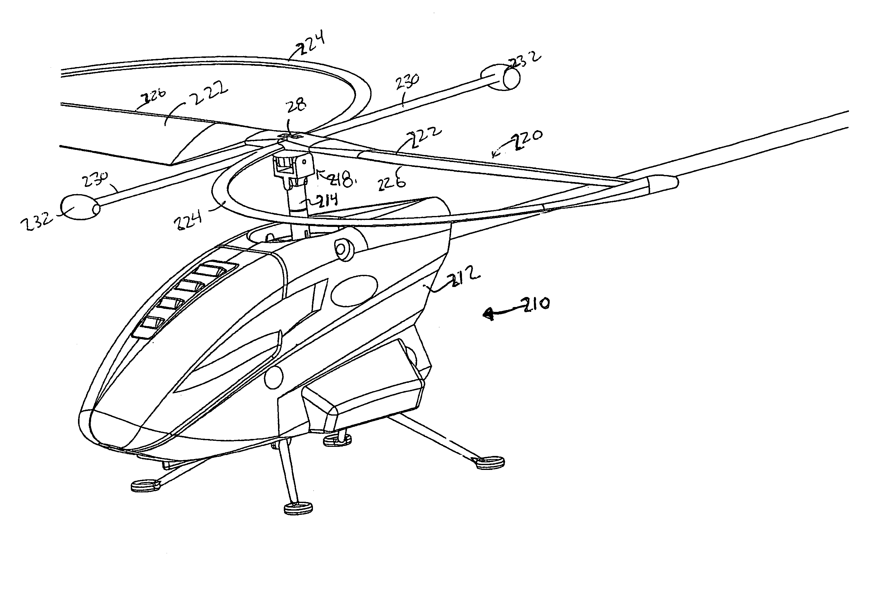
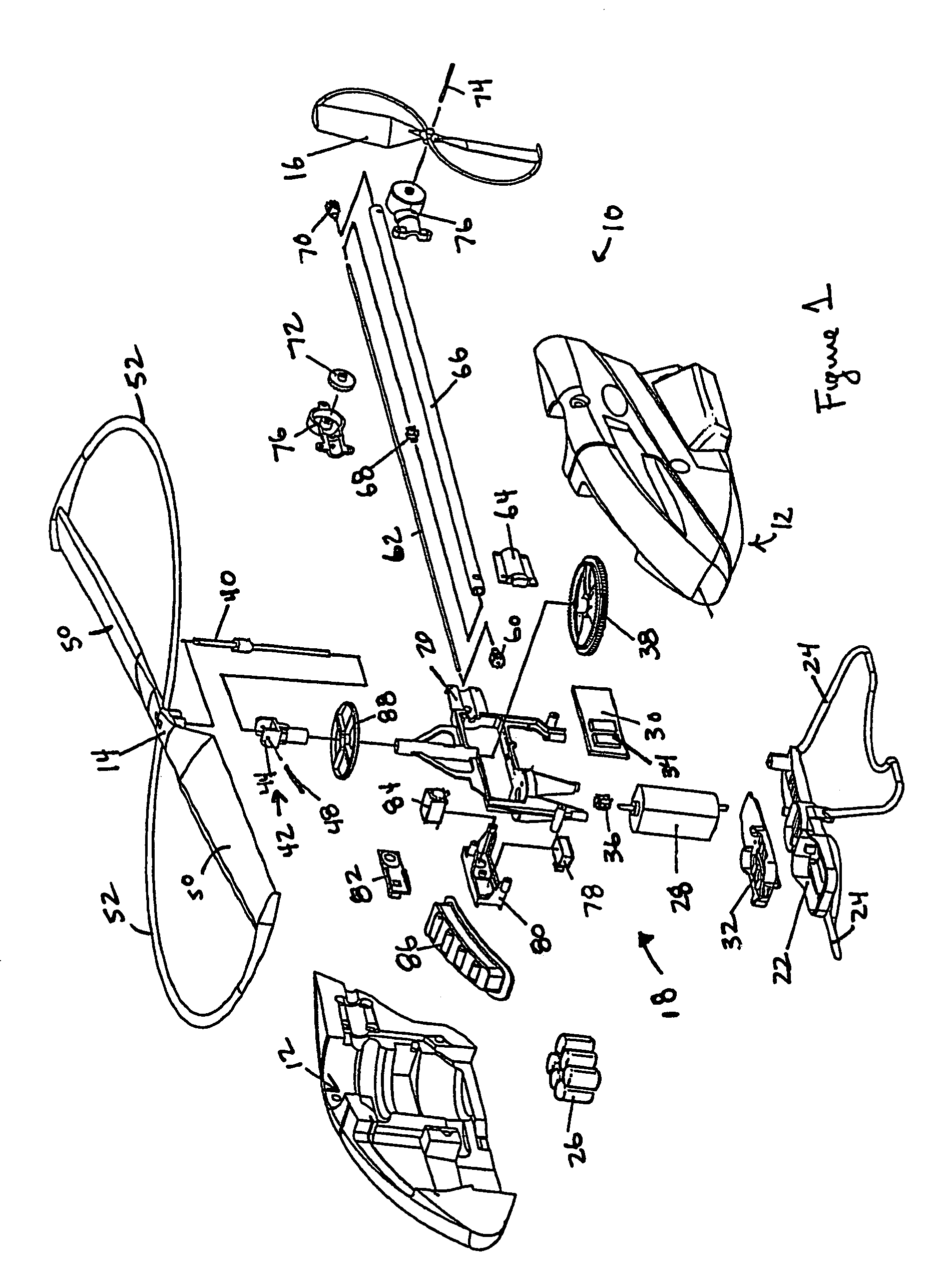
[0029]A propeller related vehicle, is illustrated in but one embodiment of the present invention as a helicopter 10, depicted in FIG. 1. Like a typical helicopter the present embodiment includes an airframe 12 that houses the electronics and mechanical components as well as a chassis. The chassis is preferably designed as a two piece chassis defined as an upper chassis 20 and a lower chassis 22. Attached to the lower chassis 22 are landing skids 24 such that the helicopter 10 may rest on a given surface.
[0030]The helicopter 10 includes a main prope...
PUM
Abstract
A propeller related vehicle in accordance with one embodiment of the present invention is described as a helicopter having an airframe housing a motor mechanism for powering a main propeller attached to a main drive shaft that extends vertically through the airframe and for powering a tail rotor. The helicopter further includes a horizontal stabilizing mechanism attached between the main propeller and the main drive shaft, which permits the main propeller to freely pivot about the main drive shaft independently from the airframe. As such when the main propeller is rotating and the main propeller begins to pitch, the rotating main propeller has a centrifugal force created by the rotation thereof and will tend to pivot about the horizontal stabilizing mechanism in a manner that offsets the pitch such that the helicopter remains in a substantially horizontal position. In addition various main propeller configurations may be employed that provide additional self-stabilization.
Description
CROSS-REFERENCE TO RELATED APPLICATIONS[0001]This application is a continuation of U.S. patent application Ser. No. 10 / 277,691, filed on Oct. 23, 2003 which is a continuation in part of U.S. Pat. No. 6,659,395, which is a continuation in part of application Ser. No. 29 / 158,996, filed on Apr. 15, 2002, and a continuation in part of application Ser. No. 29 / 158,997, filed on Apr. 15, 2002, and which claims the benefit of U.S. Provisional Application 60 / 337,670 filed on Nov. 7, 2001 and Provisional Application 60 / 348,891, filed on Jan. 14, 2002.FIELD OF THE INVENTION[0002]This invention relates generally to propellers and propeller related vehicles and more particular to vehicles, such as air, land and water vehicles, that use or incorporate propellers to create lift or as a means for propulsion, and for most aspects of the present invention relate to air based vehicles designed for the toy or hobby industry.BACKGROUND OF THE INVENTION[0003]While the present invention is related in part...
Claims
Application Information
Patent Timeline
Application Date:The date an application was filed.
Publication Date:The date a patent or application was officially published.
First Publication Date:The earliest publication date of a patent with the same application number.
Issue Date:Publication date of the patent grant document.
PCT Entry Date:The Entry date of PCT National Phase.
Estimated Expiry Date:The statutory expiry date of a patent right according to the Patent Law, and it is the longest term of protection that the patent right can achieve without the termination of the patent right due to other reasons(Term extension factor has been taken into account ).
Invalid Date:Actual expiry date is based on effective date or publication date of legal transaction data of invalid patent.

