Self centering sill plate retainer with opposing wings

a retainer and sill plate technology, applied in the field of fasteners, can solve the problems of inability of the fastener to compensate, the inability of the commonly used fastener to accommodate the slight rotation of the assembled joint, and the inability of the fastener to adapt to the assembled join

Active Publication Date: 2007-02-20
NEWFREY
View PDF57 Cites 27 Cited by
  • Summary
  • Abstract
  • Description
  • Claims
  • Application Information

AI Technical Summary

Benefits of technology

[0006]The second or deflectable wing includes a pair of male-shaped ears on opposed sides of the wing which engage a pair of retention elements joined to each of the support posts. When the male ear is engaged in the retention elements, the second wing is prevented from returning to its initial position but is still deflectable in an inward direction to allow insertion of the fastener into an aperture of the vehicle.

Problems solved by technology

A drawback of commonly used fasteners is the inability of the fastener to compensate for misalignment between the fastener location and the aperture in the automobile.
A further drawback is the inability of commonly used fasteners to accommodate slight rotation of the assembled joint in order to compensate for further misalignment between the fastener and the aperture of the automobile.
Still another drawback of some existing fastener designs is an all metal body of the fastener itself.
An all-metal fastener can result in corrosion between the metal contact surfaces between the fastener and the automobile as well as causing damage to the area of the aperture of the automobile upon insertion of the fastener or removal of the fastener.
Some fastener designs have a further drawback by requiring two pieces.
This obviously increases complexity of assembly as well as requiring the cost and maintenance of a two part system during vehicle construction.

Method used


Image

  • Self centering sill plate retainer with opposing wings
  • Self centering sill plate retainer with opposing wings
  • Self centering sill plate retainer with opposing wings

Examples


Embodiment Construction

[0018]The following description of the preferred embodiment is merely exemplary in nature and is in no way intended to limit the invention, its application, or uses.

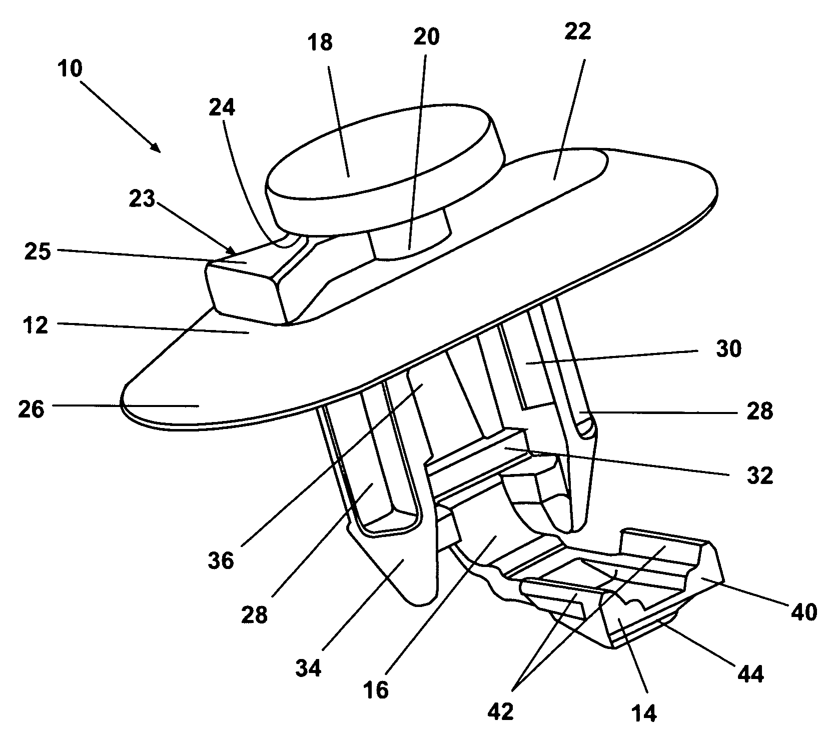
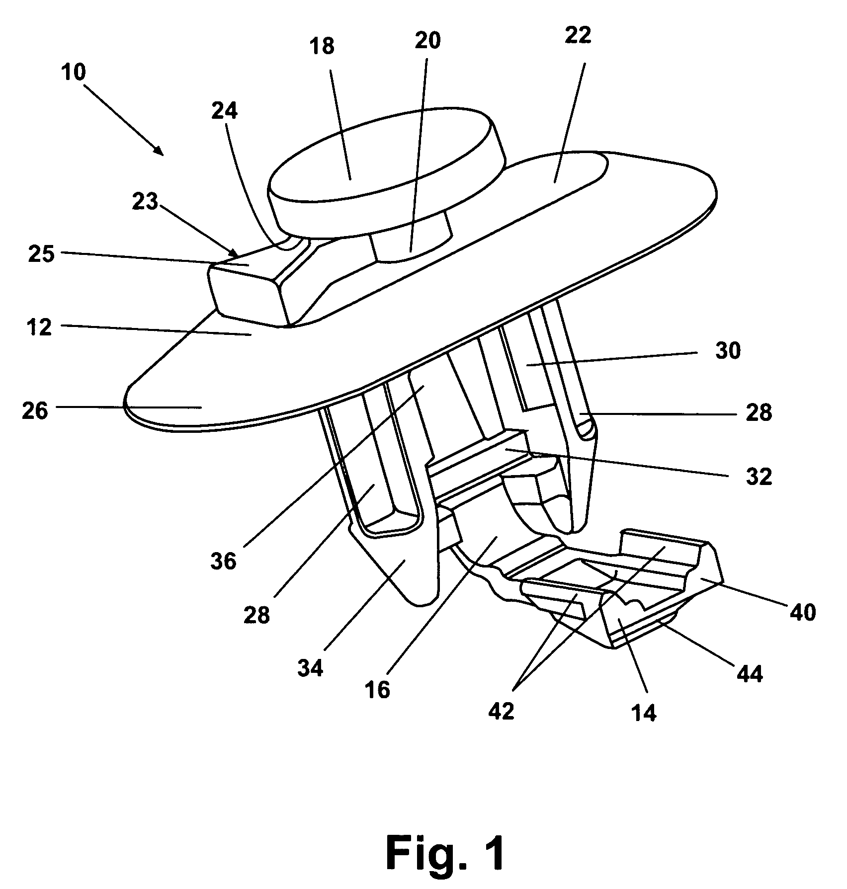
[0019]According to the preferred embodiment of the present invention, and as shown in FIGS. 1 and 2, a centering retainer 10 includes a first piece 12 and a second piece 14 connected to the first 12 piece by a living hinge 16. A generally circular head 18 is connected to a neck 20. The neck 20 is connected to a top surface 22. Top surface 22 is a generally planar surface extending beyond a perimeter of head 18. An anti-rotational rib 23 is co-molded with head 18 and neck 20. Anti-rotational rib 23 includes an apex 24 adjacent a perimeter of head 18 and a V-shaped body 25 extending outwardly from apex 24. Head 18, neck 20, and anti-rotational rib 23 are co-molded with top surface 22. A co-molded flexible skirt 26 radially extends outward from a perimeter of top surface 22 and at a downward directed angle therefrom.

[0020]A...


PUM


Abstract

A one-piece molded apparatus includes a first body section having a head, a skirt, a pair of support posts joined to the skirt, and a first engagement wing. A second body section includes a second engagement wing, and a living hinge joining the second wing to the support posts. The second wing rotates about the living hinge and engages with the support posts such that at least the second wing can thereafter deflect. In another embodiment, a dog-house assembly is provided on a trim piece to mate with the apparatus. In still another embodiment, a method for forming the fasteners is provided. In yet another embodiment, a method to attach a trim piece to a vehicle is provided.

Description

[0001]This application claims the benefit of U.S. Provisional Application No. 60 / 474,833, filed May 30, 2003.FIELD OF THE INVENTION[0002]The present invention relates generally to fasteners and more specifically to a fastener design for joining trim pieces to the surfaces of automobiles.BACKGROUND OF THE INVENTION[0003]For automotive applications, fasteners are used to join trim pieces to sections or metal body portions of the automobile. The requirements for these fasteners are that they be insertable into apertures of the automobile and meet standards for both insertion pressure of the insert as well as minimum pullout retention force such that the insert can be removed without damaging the trim piece. Common fastener designs include two or more flexible wings which deflect inwardly upon insertion of the fastener and expand by spring force to hold the fastener within a slot formed in the automobile. A drawback of commonly used fasteners is the inability of the fastener to compensa...

Claims


Application Information

Patent Timeline
Patent Type & Authority Patents(United States)
IPC IPC(8): B25G3/36F16B5/06F16B5/12F16B19/00
CPCF16B5/123Y10S411/913Y10T24/309Y10T403/7123Y10T24/303Y10T403/75Y10T403/60Y10T403/58Y10T24/42Y10T403/7176F16B2200/69
Inventor BENEDETTI, STEVEN M
Owner NEWFREY
Why Eureka
Try Eureka