Blind rivet

a blind rivet and rivet technology, applied in the field of fastenings, can solve the problems of additional components, additional labor, and additional fasteners, and achieve the effect of reducing the cost of sheet metal fabrication

Inactive Publication Date: 2007-02-20
NEWFREY
View PDF18 Cites 15 Cited by
  • Summary
  • Abstract
  • Description
  • Claims
  • Application Information

AI Technical Summary

Benefits of technology

[0005]An objective of the present invention is to reduce the cost of producing sheet metal fabrications, by reducing the need for additional placement of fasteners to secure secondary components to the assembly.
[0006]A further objective of the present invention is to provide a means of concealing and protecting the exposed heads of blind rivets after setting.

Problems solved by technology

The provision of additional fasteners adds expense to the manufacture of the fabrication, in that not only are additional components required, but additional labour is necessary for attaching the components to the assembly.

Method used


Image

  • Blind rivet
  • Blind rivet
  • Blind rivet

Examples


Embodiment Construction

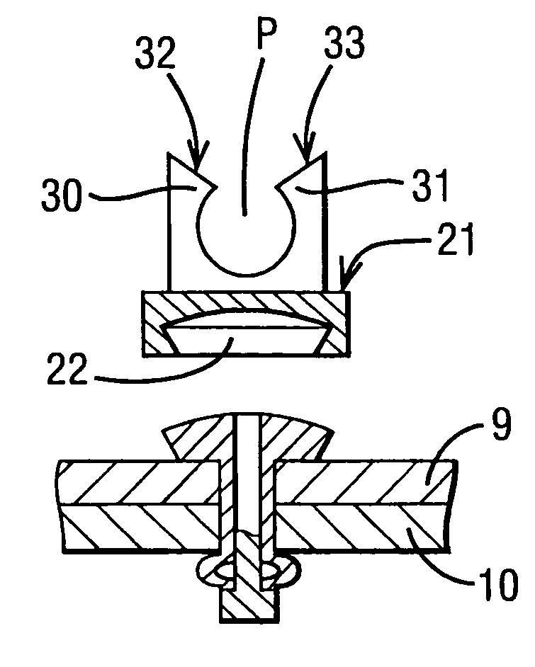
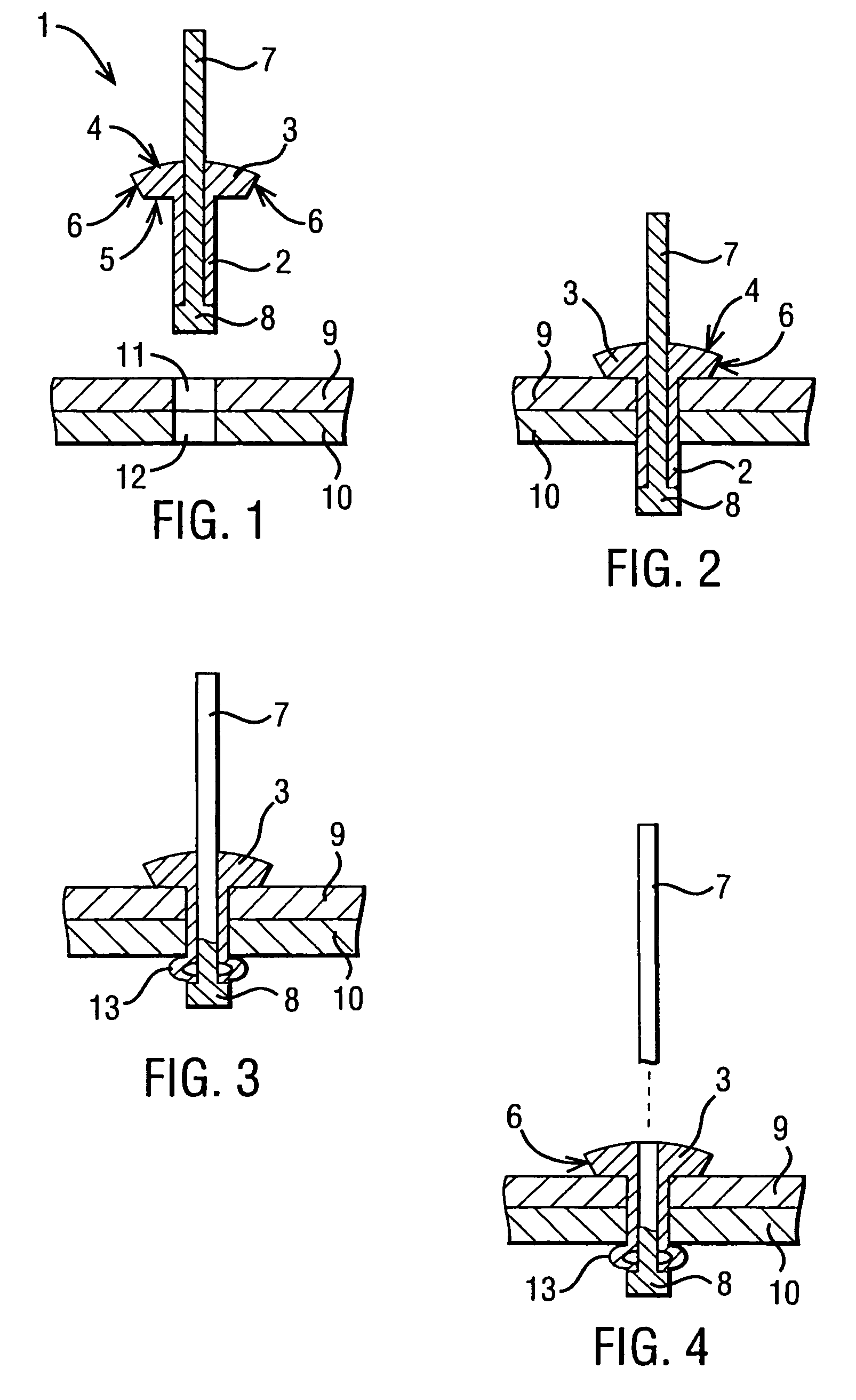
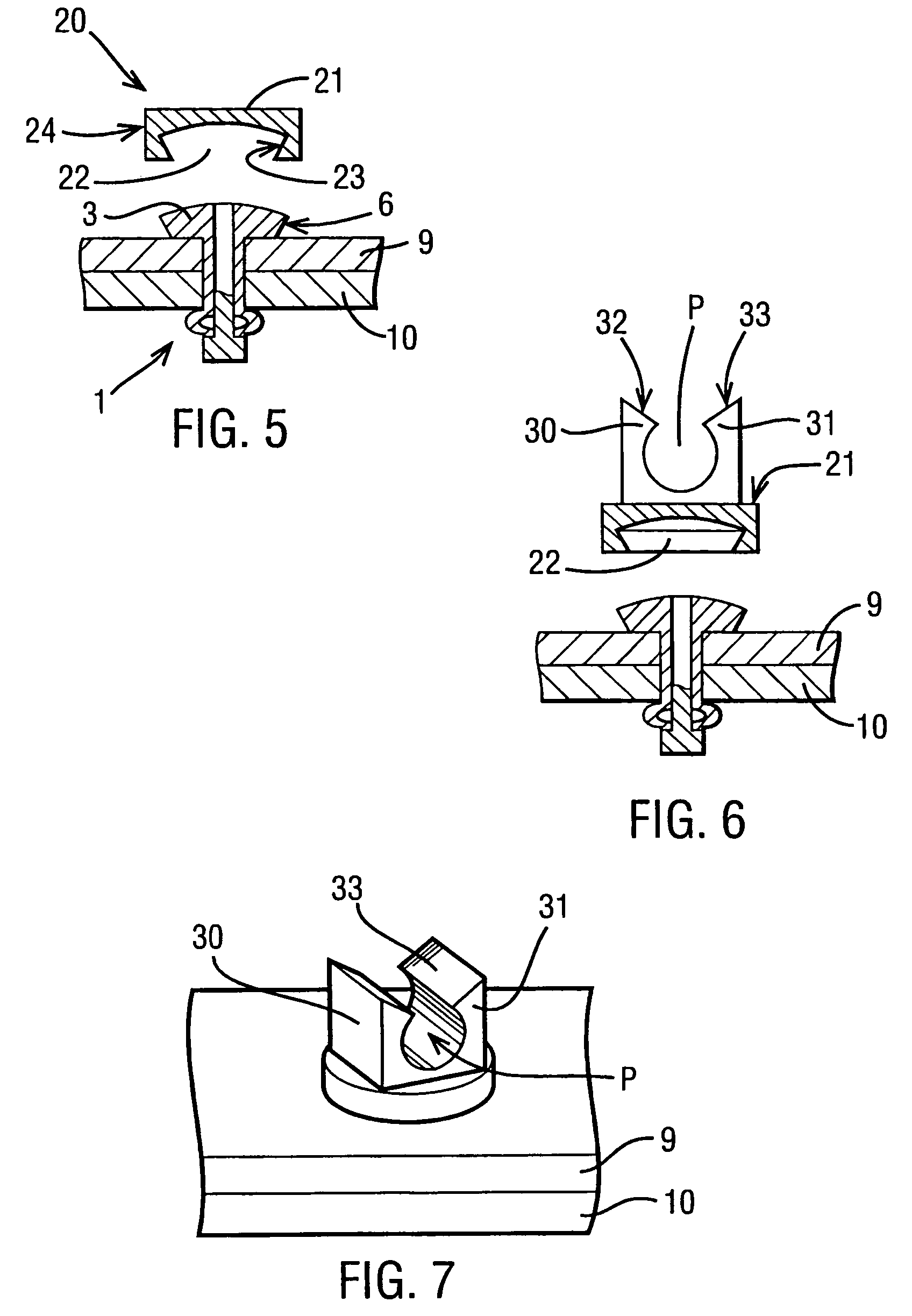
[0022]Referring now to the drawings, FIGS. 1 to 4 show the setting sequence for the rivet. The rivet 1 comprises a tubular shank 2 at the upper end of which (as shown in the Figures) is a radially outwardly extending flange 3. The upper surface 4 of the flange 3 is domed, and the undersurface 5 of the flange 3 is planar and perpendicular to the tubular shank 2. The outer peripheral surface 6 of the flange 3 is tapered inwardly and downwardly in this embodiment, to provide a conical surface tapering towards the lower end of the rivet 1. A stem 7 extends through the tubular shank 2 and protrudes beyond the domed surface 4 of the flange 3. The stem 7 extends longitudinally through the tubular shank 2, and has a radially enlarged head 8 whose outer diameter is substantially equal to the outer diameter of the tubular shank 2, in contact with the end of the shank 2 remote from the flange 3.

[0023]The sequence of FIGS. 1 to 4 shows the use of a rivet to join together two sheets 9 and 10 of ...


PUM

PropertyMeasurementUnit
resilientaaaaaaaaaa
outer diameteraaaaaaaaaa
diameteraaaaaaaaaa

Abstract

There is described an expanding blind rivet assembly having a flange (3) provided with an undercut surface facing the rivet shank. A resilient cap (20) is formed with a cavity (22) having an opening surrounded by an undercut surface (23) within the cavity, so that the cap may be snap-engaged over the flange of the rivet after setting. The cap provides abrasion and corrosion protection for the flange. The cap (20) may also be provided with securing means for securing a further component to the cap (20).

Description

CROSS-REFERENCE TO RELATED APPLICATIONS[0001]The present application is a continuation of pending International Patent Application PCT / EP02 / 09130, filed Aug. 15, 2002 which designates the United States and which claims priority of Great Britain patent application 0120020.3, filed on Aug. 16, 2001.FIELD OF THE INVENTION[0002]The present invention relates to fastenings for sheet materials, and is particularly concerned with blind rivet fastenings.BACKGROUND OF THE INVENTION[0003]A conventional blind rivet fastening has a tubular shank with an external flange at one end, and a stem extending through the shank. A first end of the stem protrudes from the flanged end of the shank, and a second end of the stem has a head whose outer diameter corresponds to the outer diameter of the shank, and which abuts the end of the shank remote from the flange. To join two sheets of material together with the rivet, aligned holes with a diameter corresponding to the external diameter of the shank are f...

Claims


Application Information

Patent Timeline
Patent Type & Authority Patents(United States)
IPC IPC(8): F16B19/10B21J15/04F16B5/04F16B2/06F16B2/08F16B5/12F16B19/00F16B37/14
CPCB21J15/043F16B2/06F16B2/08F16B37/14F16B19/008F16B19/1054F16B5/128
Inventor GUY, MICHAEL PAUL
Owner NEWFREY
Why Eureka
Try Eureka