Self cleaning hydro delivery system

a technology of hydro-dispensing system and self-cleaning, which is applied in the direction of liquid fuel engine, renewable energy generation, greenhouse gas reduction, etc., can solve the problems of electric power polluting the environment, massive environmental disturbance, and increasing costs for consumers, so as to achieve no impact on the surrounding landscape, no environmental disturbance, and heavy capital expenditur

Active Publication Date: 2007-02-20
STAGGS LELAND WAYNE
View PDF3 Cites 7 Cited by
  • Summary
  • Abstract
  • Description
  • Claims
  • Application Information

AI Technical Summary

Benefits of technology

[0006]The self-cleaning Hydro delivery system of the present invention does not require a dam, and consequently there is no impact on the surrounding landscape. The self cleaning hydro delivery system can be located beside a stream where the water table has a high-rise, at the top of a waterfall or adjacent to a mountain (The present invention can be used even though the water to the system may have to run uphill.) The self-cleaning hydro delivery system requires no central facility or long transmission network because it can be installed at the location of the consumers. Furthermore, the present system is nonpolluting since it does not require any nonrenewable resource, and it does not require a dam, heavy capital expenditures and does not change the landscape. The system of the present invention has minimal environmental impact.

Problems solved by technology

Most of these sources of electric power are not renewable and as a consequence, are increasingly expensive for the consumer.
Additionally, many of these sources of electric power pollute the environment and are undesirable from this aspect.
The pollution may include many forms of harmful byproducts such as smoke and airborne particles of harmful dust for example from coal burning plants and carbon dioxide from gas burning facilities.
The coal burning plants use coal as a fuel which is provided for example by strip mining which can cause massive environmental disturbances.
However, nuclear generating plants have created public hostility and fear, and in addition, these nuclear generating plants have experienced exploding construction costs and has an additional problem of disposing of spent radioactive fuel rods.
Hydroelectric power is environmentally clean to produce electricity but can be very expensive and environmentally disruptive to install.
These conventional hydroelectric plants can only be situated on large rivers with sufficient flow and fall which is the distance the water must drop to build up energy enough to turn a turbine.
Usually, hydroelectric power requires constructing a large dam across the river and a large centralized generating facility with expensive transmission network to transmit the generated power to the consumer.
Necessarily, such a dam radically alters the landscape.

Method used


Image

  • Self cleaning hydro delivery system
  • Self cleaning hydro delivery system
  • Self cleaning hydro delivery system

Examples


Embodiment Construction

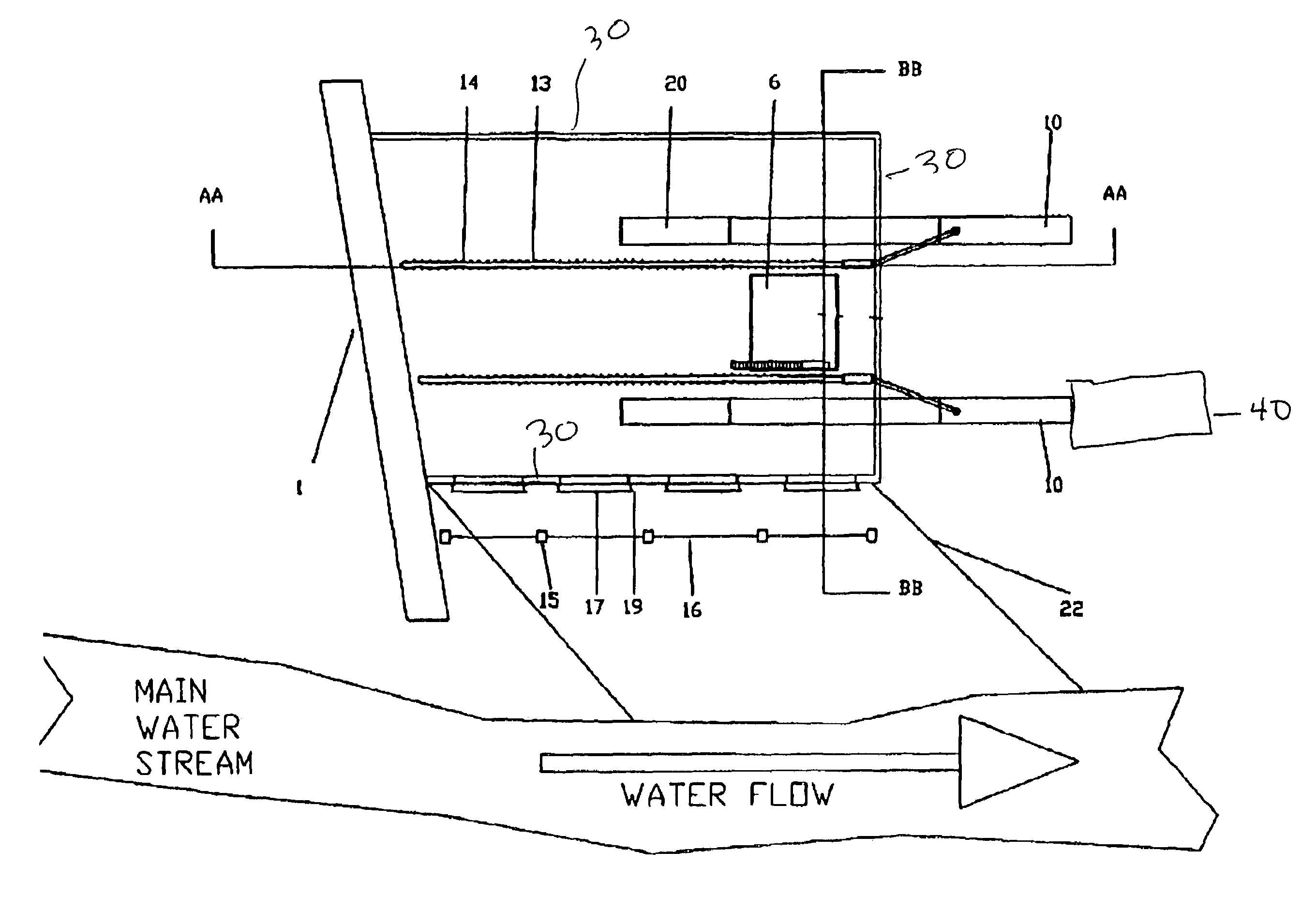
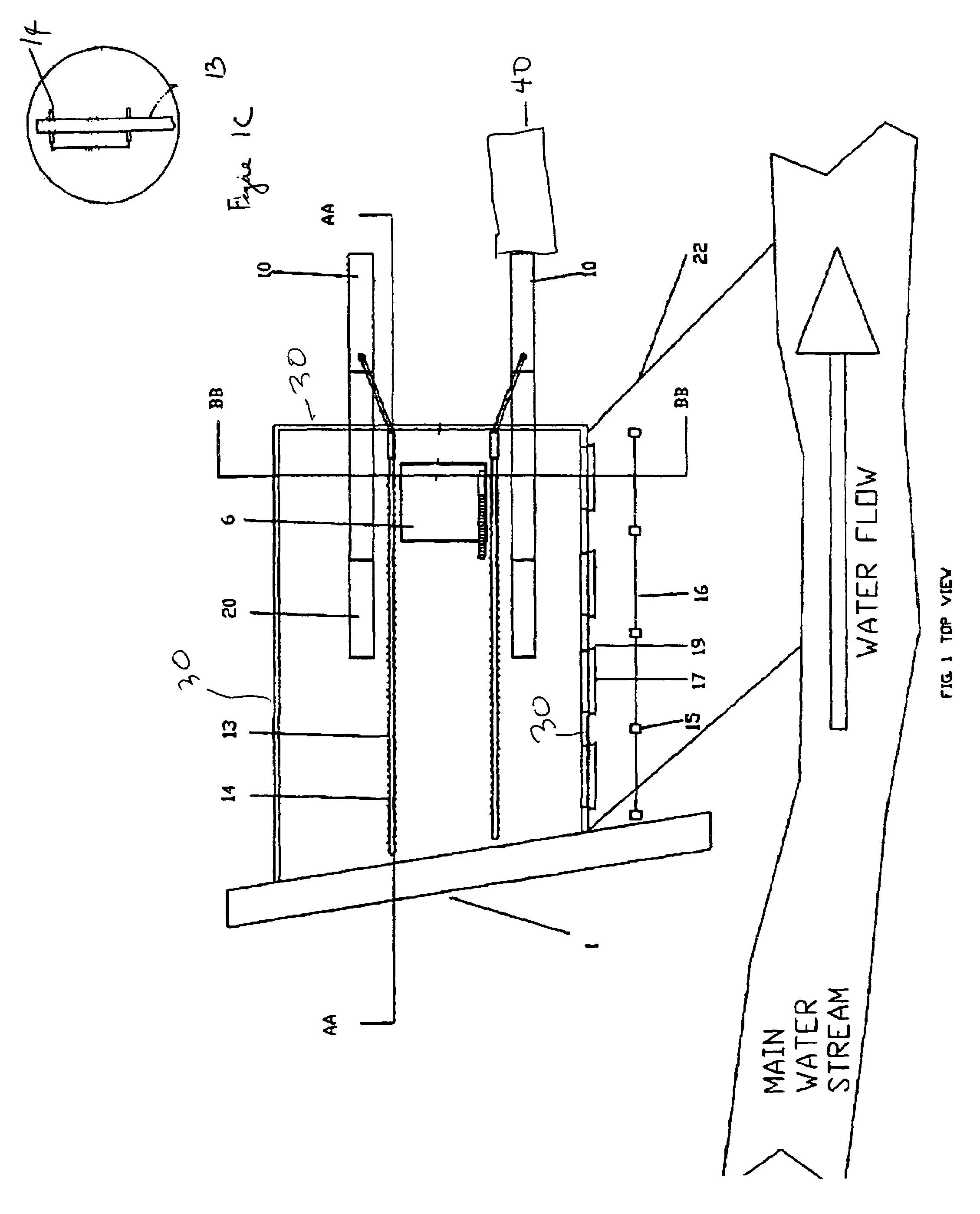
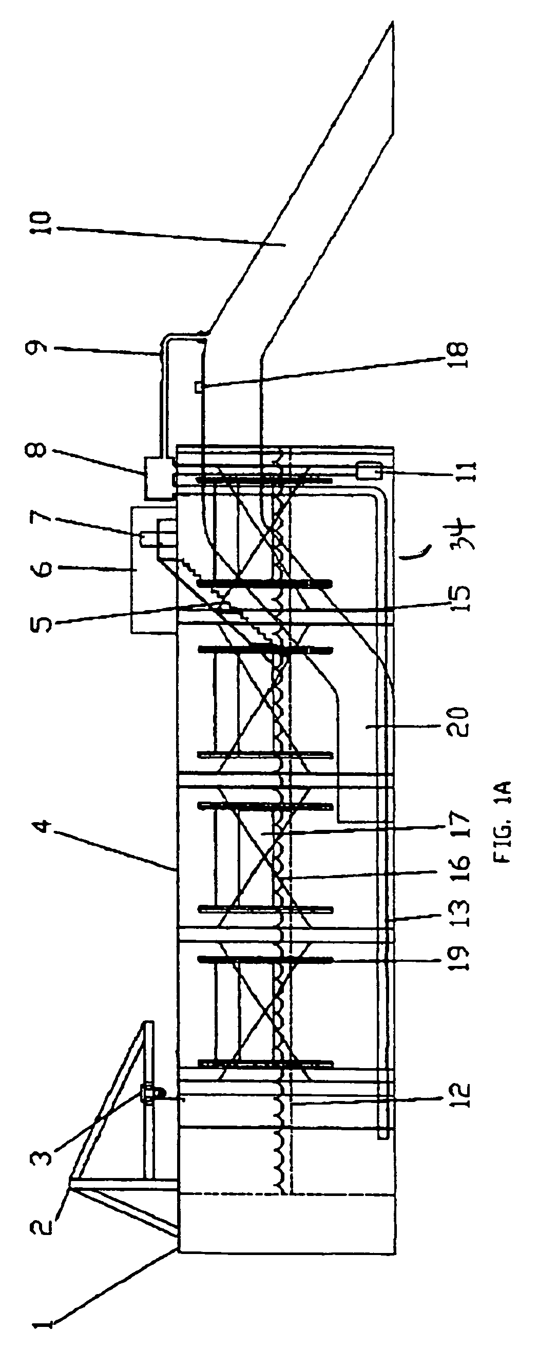
[0017]FIG. 1 shows the self-cleaning hydro delivery system 100 which includes structure walls 30 and a high impact wall 1 to provide additional protection for the system 100 from the debris that flows in the water stream 32 under high volume conditions. Positioned along the waterside wall 30 are several guard beams 15 which are secured in the bank of the water stream 32 and support interlocking cables 16 which may be made from steel to the prevent large debris from entering the self cleaning hydro delivery system 100. The waterside wall 30 includes at least one water inlet door 17 which opens and closes to regulate the amount of water from the water stream 32 that enters the self cleaning hydro delivery system 100. The support interlocking cable 16 is positioned in front of the water inlet door 17. FIG. 1 shows a water inlet trough 22 to allow water to flow from the water stream 32 to the water inlet door 17. The water inlet trough 22 could be replaced with other means such as a pip...


PUM


Abstract

A system for supplying a fluid to a turbine includes an inlet for allowing the fluid to enter the turbines, a filter to filter the fluid, and a pump apparatus to pressurize the fluid and to mix the pressurized fluid with the un-pressurized fluid at a location in the neighborhood of the inlet.

Description

PRIORITY[0001]The present invention claims priority based on 35 USC 119 for provisional application Ser. No. 60 / 580,589 filed on Jun. 18, 2004.FIELD OF THE INVENTION[0002]The present invention relates to a cleaning system and in particular to a self-cleaning Hydro system.BACKGROUND OF THE INVENTION[0003]The industrial society of today depends substantially on a source of economical electric power. Most of these sources of electric power are not renewable and as a consequence, are increasingly expensive for the consumer. Additionally, many of these sources of electric power pollute the environment and are undesirable from this aspect. The pollution may include many forms of harmful byproducts such as smoke and airborne particles of harmful dust for example from coal burning plants and carbon dioxide from gas burning facilities. The coal burning plants use coal as a fuel which is provided for example by strip mining which can cause massive environmental disturbances. Electric power ca...

Claims


Application Information

Patent Timeline
Patent Type & Authority Patents(United States)
IPC IPC(8): F03B13/12F03B11/08F04D27/02
CPCF03B11/08Y02E10/226Y02E10/20
Inventor STAGGS, LELAND WAYNE
Owner STAGGS LELAND WAYNE
Why Eureka
Try Eureka