Compact structure of a new biosensor monitor

a biosensor and monitor technology, applied in the field of biosensor monitor design, can solve the problems of inconvenient blood collection process by such lancing device with both hands, large size, and high cost of packaging space, and achieve the effect of small siz

Inactive Publication Date: 2007-02-20
CHANG YU HONG
View PDF12 Cites 99 Cited by
  • Summary
  • Abstract
  • Description
  • Claims
  • Application Information

AI Technical Summary

Benefits of technology

[0005]It is therefore the objective of this new design to provide a mechanism with the monitor and blood lancer in one piece, small in size and only one finger to operate, which will be free from the inconvenience and d drawbacks associated with the conventional biosensor device.
[0006]The mechanical structure of this monitor within which there is a circuit board with a receiver slot for the test strip to be inserted in. Signals received from the reaction of the reagent on the test strip with the applied blood will be analyzed via the built-in CPU (Central Processing Unit) and shown on the LCD (Liquid Crystal Display) screen and, or, be transmitted through the communication port (USB, Serial or Parallel Port) to the computer for data acquisition and analysis. This monitor also houses a lancing device, which composes of a number of parts and springs, to pierce the needle of the lancet into the skin for a tiny drop of blood. This lancing device can be installed a disposable lance. Replacing the used needle with a new one automatically reloads the lancing device ready to be triggered for blood inoculation, upon the touch one finger only. With this structural design, blood specimen can be easily collected with the touch of, say, a finger onto the lancing device to trigger the release of the lancet, and be applied onto the reagent of the test strip to determine the results of its electrochemical reaction through the measurement of electrical current or voltage which will then be processed via the built-in CPU to display on the LCD screen.

Problems solved by technology

Although both are portable, however, it requires more box space to put in both the monitor and blood lancer, making it rather bulky and inconvenient to carry around.
Furthermore, to use a conventional lancing device requires two hands, one hand for triggering the lancing device to prick onto the fingertip of the other hand.
Such conventional design of the monitor and the lancing device means two separate individual items, resulting in higher costs and packaging space.
Moreover, the blood collection process by such lancing device with both hands is rather in inconvenient.

Method used


Image

  • Compact structure of a new biosensor monitor
  • Compact structure of a new biosensor monitor
  • Compact structure of a new biosensor monitor

Examples


Embodiment Construction

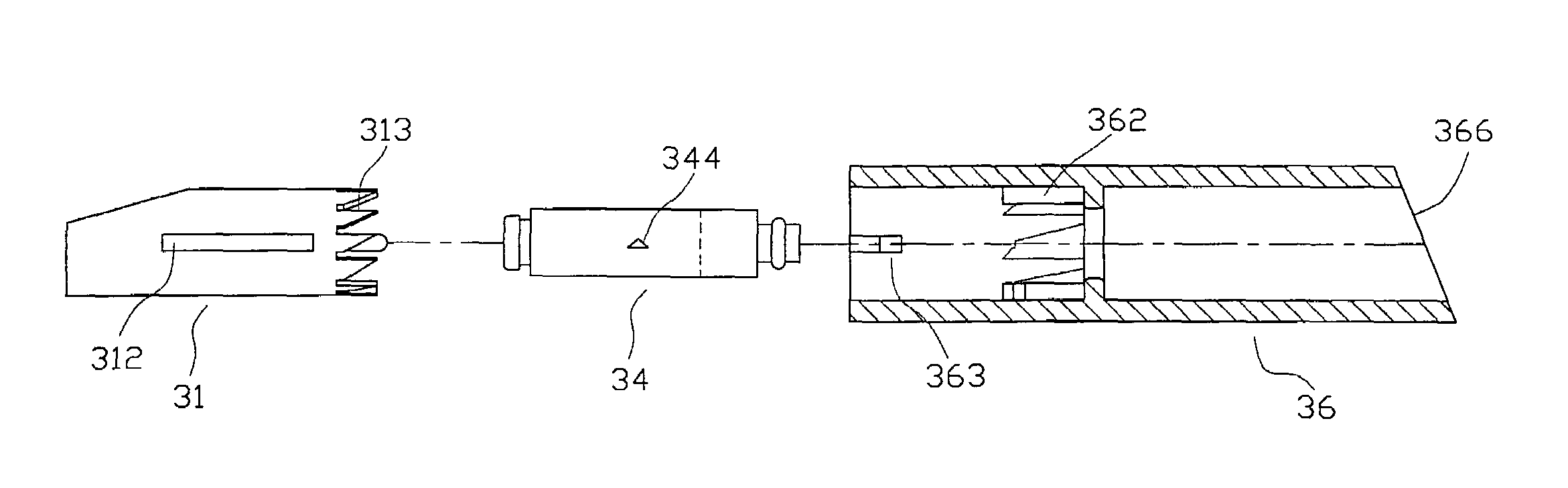
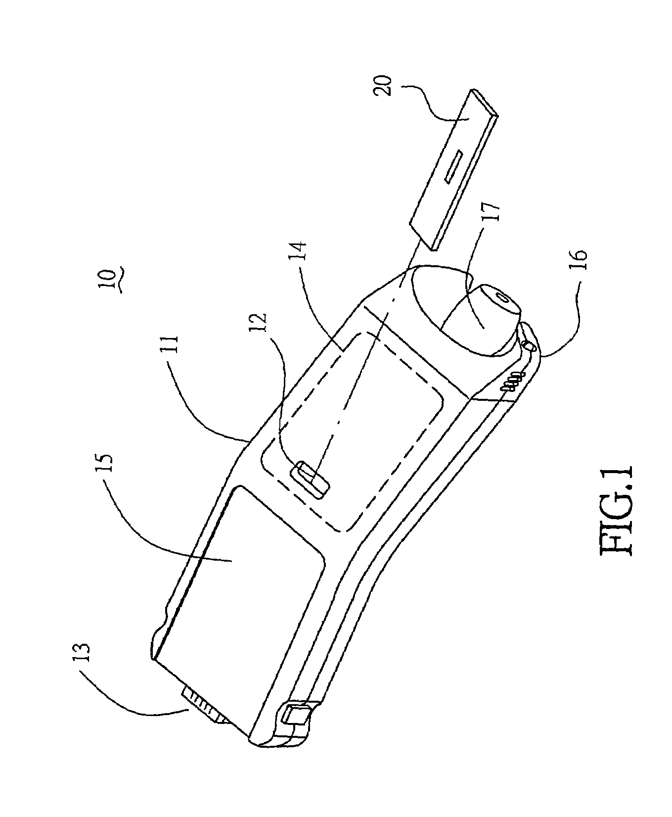
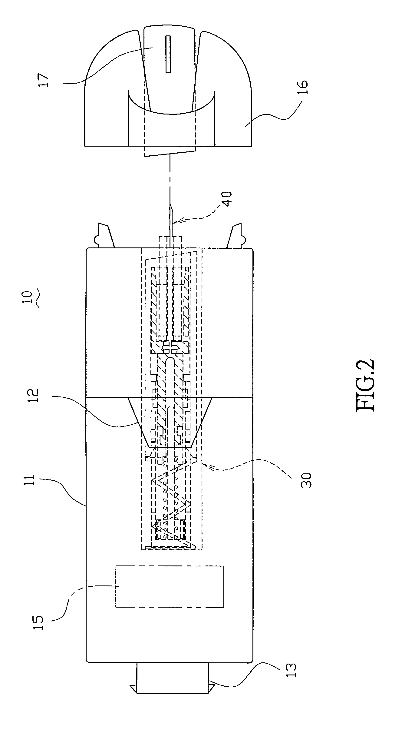
[0019]Referring to the drawings in detail, FIG. 1, the schematic view of the biosensor monitor pursuant to teachings of the present invention, shows a test strip 20 into the opening 12 on the upper protective cover 11 under which an electronic circuit board 14 is placed to measure the electrochemical response of the test strip with the added drop of blood, and on which a LCD screen 15 displays the results of the processed signals from the circuit board 14, and on which a communication port (USB, serial or parallel) 13 transmits the processed signals to the computer for data acquisition and analysis. Connected to this upper protective cover 11 is a protective cap 16 for the lancet, not shown, on which there sits a lancet cover 17. To have more insight into the mechanism of the monitor 10, FIG. 2 illustrates the positional relationship of the several components of the monitor. A number of components constitute the lancing device 30 situated inside the upper protective cover 11. A lanc...


PUM


Abstract

The invention discloses a biosensor monitor with a housing to accommodate a printed circuit board for data analysis from the electrochemical reaction on the test strip, a lancing device for blood inoculation which requires only one finger to activate the release of a lancet. This new monitor includes a biosensor monitor and the lancing device to make it more compact in size.

Description

BACKGROUND OF THE INVENTION[0001](a) Field of the Invention[0002]This invention discloses the design of a biosensor monitor with a built-in lancing device for the convenience of the diabetic patients.[0003](b) Description of the Prior Art[0004]All diabetic patients generally require a glucose monitor and a lancing device. Although both are portable, however, it requires more box space to put in both the monitor and blood lancer, making it rather bulky and inconvenient to carry around. Sometimes the lancing device is not present or lost, when it is time to perform a glucose measurement. Furthermore, to use a conventional lancing device requires two hands, one hand for triggering the lancing device to prick onto the fingertip of the other hand. Such conventional design of the monitor and the lancing device means two separate individual items, resulting in higher costs and packaging space. Moreover, the blood collection process by such lancing device with both hands is rather in inconv...

Claims


Application Information

Patent Timeline
Patent Type & Authority Patents(United States)
IPC IPC(8): A61B5/00B65D81/00A61B5/15
CPCA61B5/1411A61B5/15186A61B5/14532A61B5/150022A61B5/150183A61B5/150358A61B5/150412A61B5/150854A61B5/15087A61B5/15111A61B5/15117A61B5/1519A61B5/15194A61B5/157
Inventor CHANG, YU-HONG
Owner CHANG YU HONG
Why Eureka
Try Eureka