
Steering column module

a technology of steering column and module, which is applied in the direction of contact operating parts, contact mechanisms, transportation and packaging, etc., can solve the problems of inefficiency of the operation of exchanging meters, junction blocks, and other problems, and achieve the effect of improving the efficiency of the exchanging operation and the mounting of the combination meter

Inactive Publication Date: 2007-02-20
PANASONIC CORP +1
View PDF15 Cites 15 Cited by
  • Summary
  • Abstract
  • Description
  • Claims
  • Application Information

AI Technical Summary

Benefits of technology

The present invention provides a steering column module for a vehicle that improves the efficiency of assembly and exchange operations, reduces the number of parts and wire harnesses, and enhances recycling ability. The module includes a cover body accommodating at least one of an electric junction block and a meter. The efficiency of mounting and exchanging parts around the steering column is enhanced, and the recycling ability is enhanced. The module further includes at least one switch and a meter cluster accommodating the electric junction block, meter, and switch. The parts are combined together in the module, reducing the number of parts to be mounted and the time and labor required for assembly. The meter is directly connected to the electric junction block or the engine room-side wire harness, reducing the number of wire harnesses and the number of connections, improving reliability. The combination meter is a combination of a turn switch, wiper switch, hazard switch, and ignition switch. The efficiency of mounting and exchanging parts is enhanced, and the recycling ability is enhanced.

Problems solved by technology

In such a configuration, it is difficult to connect the engine room-side wire harness directly to the meter mounted in the instrument panel.
Therefore, the number of the mounting operations in the production of a vehicle increased, and the fixing structure is limited to the type which enabled the mounting operation to be carried out only from a predetermined direction of the assembling line.
Therefore, the operation for exchanging the meters, the junction block and so on, as well as the disassembling operation, are not efficient.

Method used


Image

  • Steering column module
  • Steering column module
  • Steering column module

Examples


Embodiment Construction

[0042]Preferred embodiments of the invention will now be described with reference to the accompanying drawings. In the drawings, identical constituent elements will be designated by identical reference numerals, respectively.

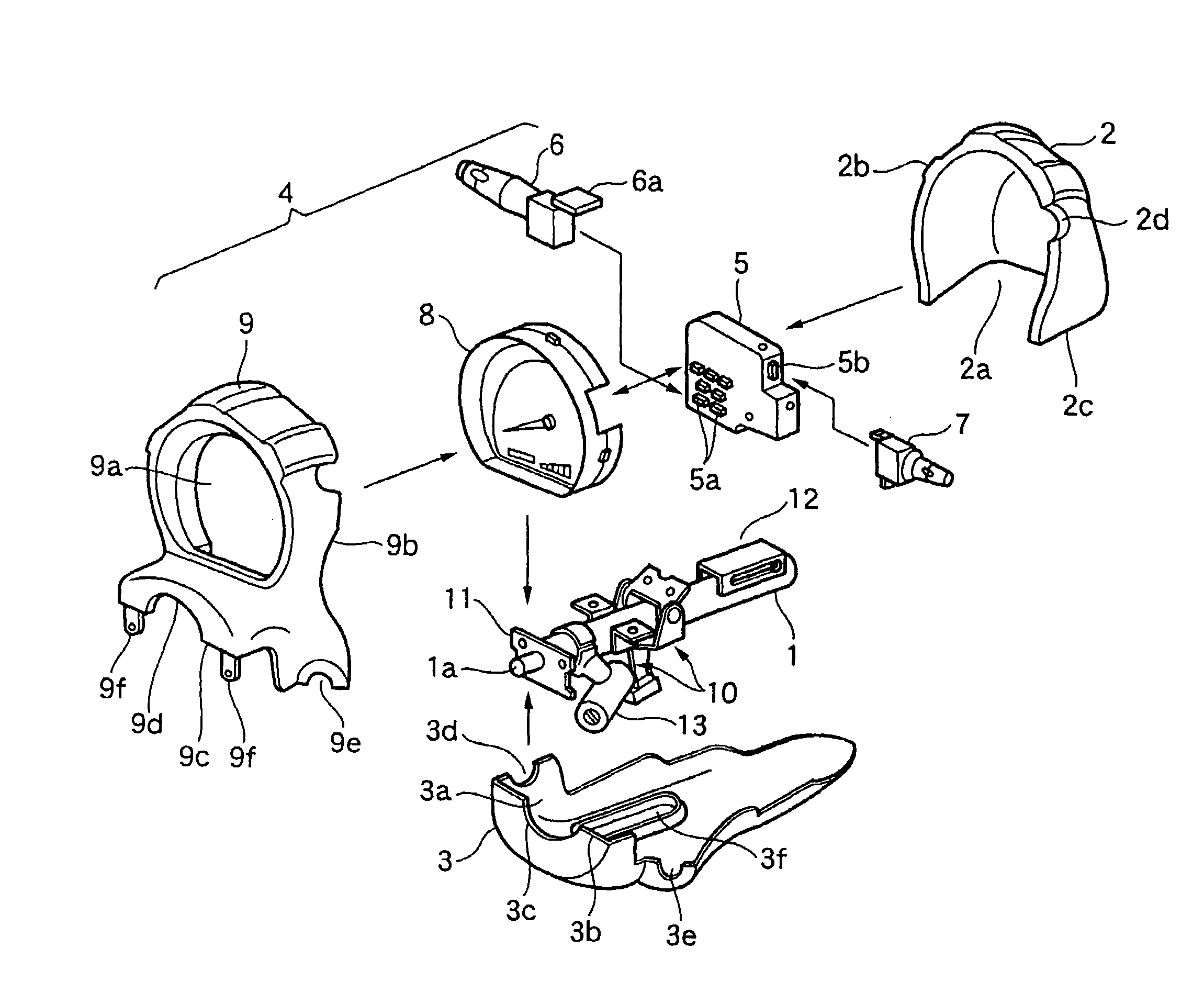
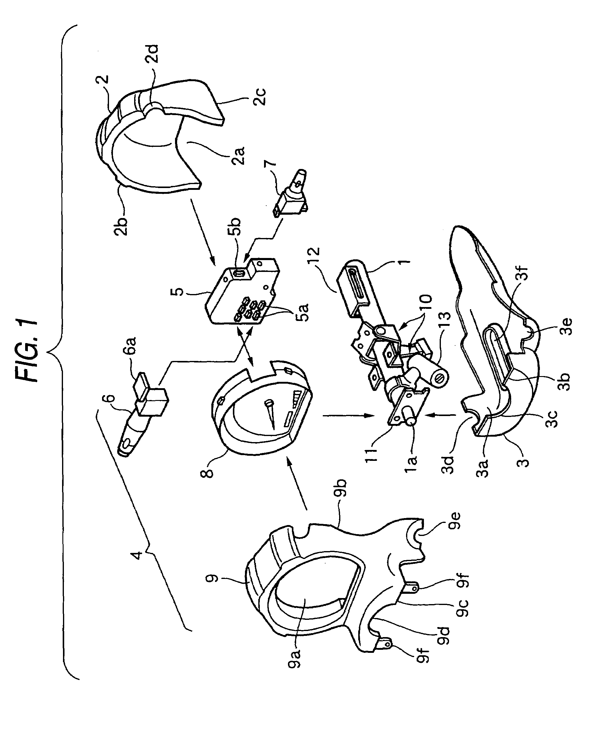
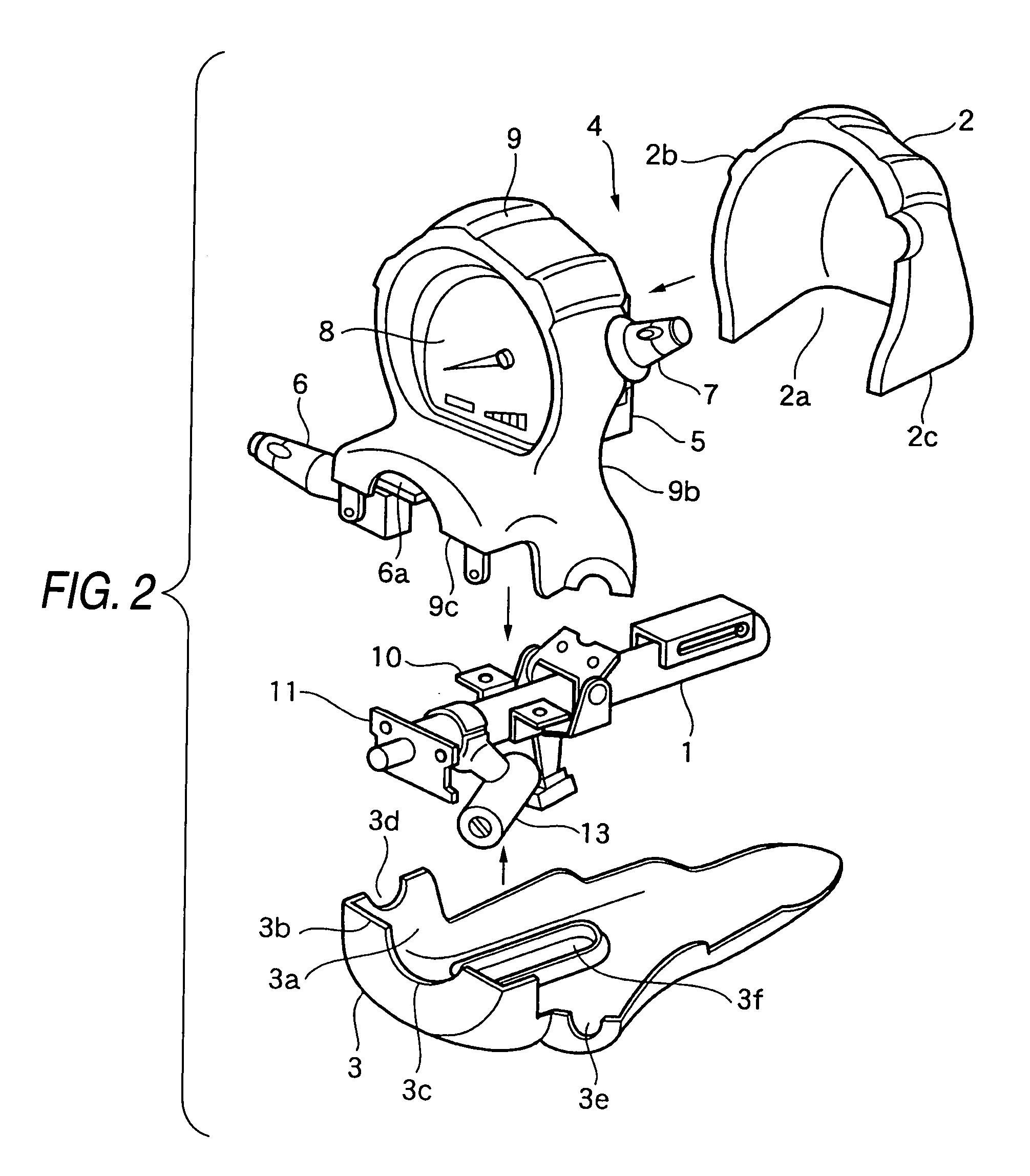
[0043]As shown in FIG. 1, a steering column module according to a first embodiment comprises a steering column cover, composed of an upper column cover 2 and a lower column cover 3, and a meter module 4, and this steering column module is mounted on a steering post 1. A steering shaft 1a, on which a steering wheel 14 is mounted, is passed through the steering post 1, and brackets 10, a mounting plate 11 and an ignition switch 13 are fixedly secured to the steering post 1.

[0044]The upper column cover 2 has a receiving recess 2a formed by a side edge portion 2b and a lower edge portion 2c, and a notch 2d, through which a wiper switch 7 is passed when this module is assembled, is formed in the side edge portion 2b.

[0045]The lower column cover 3 has a receiving rec...


PUM


Abstract

A steering column cover body accommodates therein at least one of an electric junction block, a meter and at least one switch which are directly connected with each other. The switch includes at least one of a turn switch, a wiper switch, a hazard switch and an ignition switch. The meter includes a circuit board on which a first circuit for driving the meter and a second circuit for driving the at least one switch is mounted.

Description

TECHNICAL FIELD[0001]This invention relates to a steering column module in which parts around an automotive steering column are combined together into a unitary construction.BACKGROUND ART[0002]Heretofore, in many cases, various meters and a junction block of an automobile have been mounted in an instrument panel, and have been located in different positions, respectively, and these parts, as well as a turn switch and a wiper switch, mounted on a column, and other switches, mounted on the instrument panel, have been individually connected to their mating parts at an assembling line.[0003]For example, as shown in FIG. 12, there is provided a wire harness 29 interconnecting a meter 8 and a junction block 5, and there is provided a wire harness 30 connecting a turn switch 6 and a wiper switch 7 to the junction block 5 or the meter 8.[0004]As another example shown in FIG. 13, although an engine room-side wire harness 15 is connected directly as a wire harness 17 to a junction block 5 th...

Claims


Application Information

Patent Timeline
Patent Type & Authority Patents(United States)
IPC IPC(8): H01H9/00B60K37/00B60Q1/14B62D1/16
CPCB60K37/00B60Q1/1461B62D1/16Y02T10/88B60Q2900/20B60K2360/685B60K37/20
Inventor ONODA, YOSHIMICHISAKAMOTO, MASAMIHAYASHI, MASAHARUTAKAMATSU, MASAHIROINOUE, HUMIONAGATA, MASAHIDETAKAO, KOUICHIMORI, SHIGEKIKOMIZO, KENICHIROU
Owner PANASONIC CORP
Learn More