Image pickup unit for endoscope

a technology for endoscopes and pickup units, which is applied in the field of endoscope image pickup units, can solve the problems of long inspection time, complicated endoscope operations, and the fact that the objective lens systems of endoscopes have not been mass produced as commercial products, and achieve good balan

Active Publication Date: 2007-02-20
OLYMPUS CORP
View PDF17 Cites 65 Cited by
  • Summary
  • Abstract
  • Description
  • Claims
  • Application Information

AI Technical Summary

Benefits of technology

[0023]An object of the present invention is to provide an image pickup unit for endoscope which has good balance between a magnification at a center portion and that at a marginal portion of an image, a small outside diameter, a field angle which is changed little due to variations of parts and assembly, and a maximum field angle of 150° or larger.

Problems solved by technology

However, this medical endoscope requires a long time for observing the space such as an interior of the coelom without overlooking, thereby requiring a long inspection time.
However, these objective lens systems for endoscope have not been mass manufactured as commercial products.
An endoscope which has a maximum field angle on the order of 90° to 140° is problematic in that the endoscope requires complicated and a long time operations since the endoscope requires an operation to bend a tip of the endoscope for observing a reverse side of a fold, for example, when the endoscope is used for observing an object having a fold in a tubular coelom such as a colon.
Hei 4-275514 is a lens system which consists of three lens components of four lens elements and is problematic in that the lens system can difficultly be manufactured stably since a change of a field angle of the lens system is remarkably influenced by manufacturing errors of the lens elements, manufacturing errors of a lens barrel and manufacturing errors at an assembling stage of an image pickup unit, the influences are remarkable in particular.
Furthermore, this objective lens system for endoscope is inconvenient for observation since the lens system remarkably distorts marginal portions of an image, thereby collapsing an image of an object at marginal portions.
Therefore, this objective lens system does not permit observing an enlarged image of a portion which is to be observed in details.
Furthermore, this objective lens system has a most object side surface which is remarkably protruding, whereby a lens element is easily damaged and can not drain water well.
These lens systems therefore require high precisions for the aspherical surfaces and will degrade image qualities if the aspherical surfaces are formed with low precisions.
In addition, the aspherical surfaces which can hardly be worked with high precisions have low yields and require high manufacturing costs.

Method used


Image

  • Image pickup unit for endoscope
  • Image pickup unit for endoscope
  • Image pickup unit for endoscope

Examples


first embodiment

[0120]the image pickup unit for endoscope according to the present invention has a composition shown in FIG. 7 in which an objective optical system having numerical data which is listed below is combined with a solid-state image pickup device on which a color filter is arranged for each picture element.[0121]IH=1.2 mm, 2ω=165.6°, f=1.005 mm, fI=−1.102 mm r1=7.135 mm, D=1.582 mm, LH=1.159 mm, IH1=1.138 mm IH2=0.839 mm, W=2.200 mm, Fno.=9.237, p=0.0025 mm

[0122]

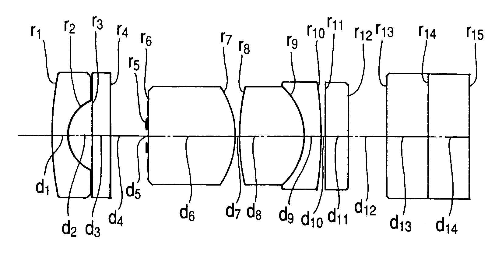
r1 = 7.135d1 = 0.36n1 = 1.88815ν1 = 40.76r2 = 0.84d2 = 0.52r3 = ∞d3 = 0.4n2 = 1.52498ν2 = 59.89r4 = ∞d4 = 0.8r5 = ∞ (stop)d5 = 0.03r6 = ∞d6 = 1.88n3 = 1.88815ν3 = 40.76r7 = −1.972d7 = 0.09r8 = 4.925d8 = 1.45n4 = 1.73234ν4 = 54.68r9 = −1.446d9 = 0.36n5 = 1.93429ν5 = 18.9r10 = −8.728d10 = 0.09r11 = ∞d11 = 0.5n6 = 1.51965ν6 = 75r12 = ∞d12 = 0.83r13 = ∞d13 = 0.9n7 = 1.51825ν7 = 64.14r14 = ∞d14 = 0.9n8 = 1.61379ν8 = 50.2r15 = ∞d15 = 0

[0123]wherein a reference symbol IH represents a maximum image height, a reference symbol 2ω designat...

second embodiment

[0133]The image pickup unit for endoscope also consists, as shown in FIG. 8, of an objective optical system which is composed of a first lens unit composed of a negative meniscus lens element (r1 to r2) disposed as a first lens element, a second lens unit composed of a plano convex lens element (r6 to r7) and a cemented lens component consisting of a biconvex lens element (r8 to r9) and a negative meniscus lens element (r9 to r10), and an aperture stop (r5) disposed between the first lens unit and the second lens unit so as to be in contact with an object side surface of the plano-convex lens element in the second lens unit, and a solid-state image pickup device which is cemented to an image side surface of a cover glass plate disposed on the most image side, or an image pickup surface of the objective optical system, and generates a luminance signal for each picture element.

[0134]Furthermore, a plane parallel plate (r3 to r4) which is disposed between the first lens element and th...

third embodiment

[0141]The image pickup unit consists, as shown in FIG. 9, of an objective optical system which consists of a first lens unit composed of a negative meniscus lens element (r1 to r2) having a convex surface on the object side and disposed as a first lens element, a second lens unit composed of a cemented lens component consisting of a plane parallel plate (r6 to r7) and a plano-convex lens element (r7 to r8), and a cemented lens component consisting of a biconvex lens element (r9 to r10) and a negative meniscus lens element (r10 to r11) and having positive refractive power as a whole, and a stop (r5) disposed between the first lens unit and the second lens unit so as to be in contact with the plane parallel plate in the second lens unit, and a color solid-state image pickup device which is cemented to an image side surface of a cover glass plate (r13 to r14) and on which a filter is arranged for each picture element.

[0142]Furthermore, a plane parallel plate (r3 to r4) which is dispos...


PUM


Abstract

An image pickup unit which consists of an objective optical system and a solid-state image pickup device: the objective optical system being composed of a first negative lens unit comprising a first meniscus lens element having a convex surface on the object side and negative power, a second positive lens unit comprising a convex lens element and an aperture stop disposed between the first lens unit and the second lens unit and this image pickup unit having a small outside diameter, allowing a field angle to be changed little due to variations of parts and an assembling variation, and having a maximum field angle of 150° or larger.

Description

BACKGROUND OF THE INVENTION [0001]1. Field of the Invention[0002]The present invention relates to an image pickup unit for endoscope which consists of an objective optical system and a solid-state image pickup device, and has a maximum field angle of 150° or larger.[0003]2. Description of the Prior Art[0004]An electronic endoscope equipped with an image pickup unit which consists of an objective optical system and a solid-state image pickup device is used for observing a relatively narrow space such as an interior of a coelom.[0005]For practical use of this electronic endoscope, an endoscope unit which has a relatively large field angle is used for facilitating to find out an abnormal matter such as a diseased portion.[0006]In recent years, a medical endoscope, for example generally has a maximum field angle on the order of 90° to 140°. However, this medical endoscope requires a long time for observing the space such as an interior of the coelom without overlooking, thereby requirin...

Claims


Application Information

Patent Timeline
Patent Type & Authority Patents(United States)
IPC IPC(8): G02B13/04
CPCG02B13/06G02B23/2446G02B23/2407
Inventor KATO, TAKAYUKI
Owner OLYMPUS CORP
Why Eureka
Try Eureka