Frequency translation

a frequency translation and frequency technology, applied in the field of radio frequency communication, can solve the problems of mixing mixers often suffering from poor linearity, injected loss in signal path, and requires additional filtering or waste, so as to avoid irregularities and minimize complexity

Inactive Publication Date: 2007-02-20
APPLE INC
View PDF11 Cites 20 Cited by
  • Summary
  • Abstract
  • Description
  • Claims
  • Application Information

AI Technical Summary

Benefits of technology

[0008]The switching system may take many forms, and may be created from discrete components or may be integrated within an integrated circuit. During operation, switching elements, such as transistors, within the switching system are contro

Problems solved by technology

Unfortunately, the inherent nature of mixing results in signals with a double sideband, which requires additional filtering or wastes available channel space in the allocated frequency spectrum.
Further, the mixers often suffer from poor linearity and inject a loss in the signal path, which must often be compensated for with additional amplification.
Compensating for linearity and loss shortcomings often results in additional complexity of the circuitry required

Method used


Image

  • Frequency translation
  • Frequency translation
  • Frequency translation

Examples


first embodiment

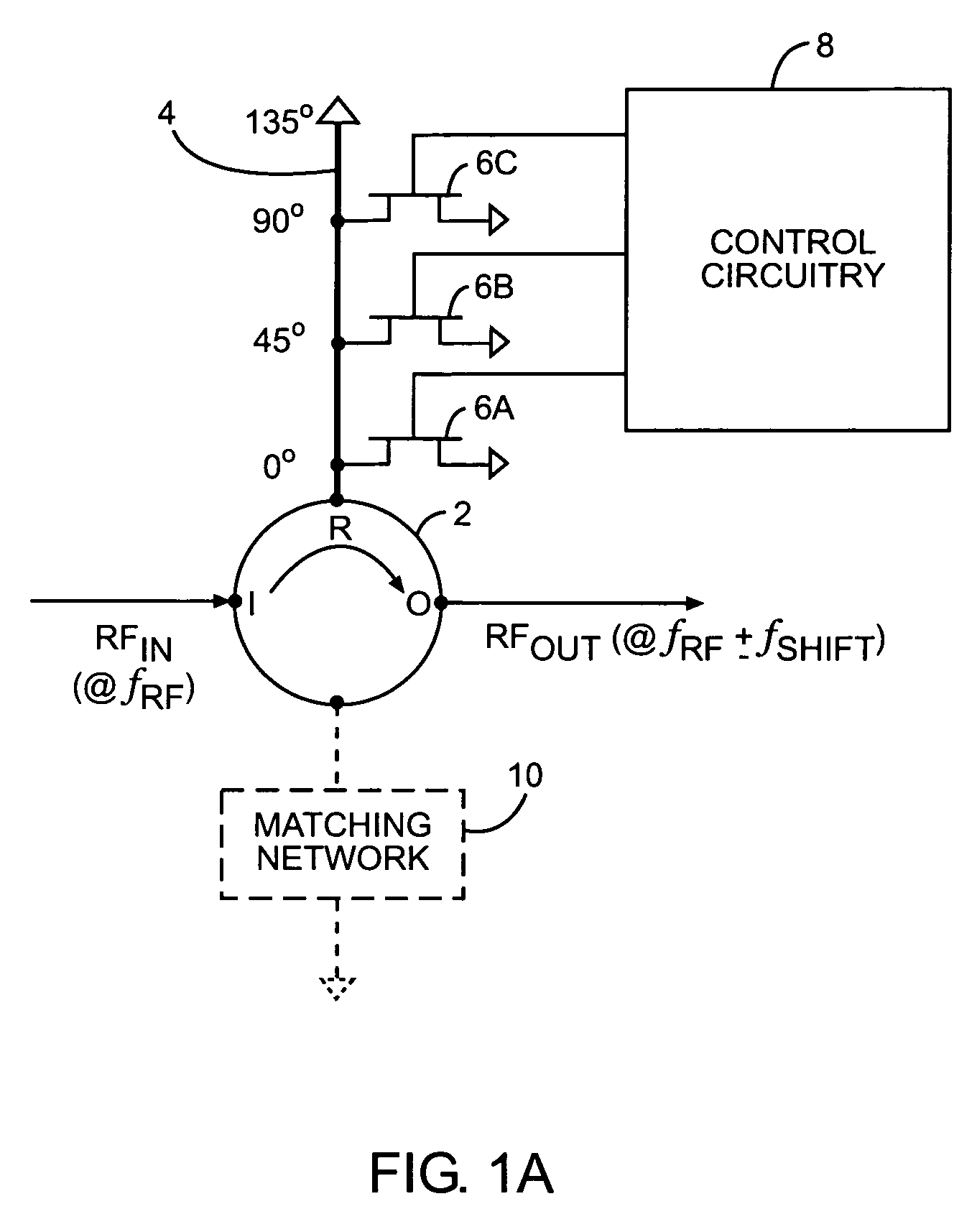
[0023]Turning now to FIG. 1, a block representation of serrodyne-based frequency translation circuitry is illustrated according to the present invention. In general, the frequency translation afforded by the present invention provides for single sideband frequency translation to essentially provide Doppler shifting of a radio frequency input (RFIN) at a first frequency, fRF, to a translated radio frequency (RFOUT) at a frequency of fRF±fSHIFT, wherein fSHIFT represents the amount RFIN is being translated in frequency. The single sideband frequency translation minimizes waste of the available frequency spectrum.

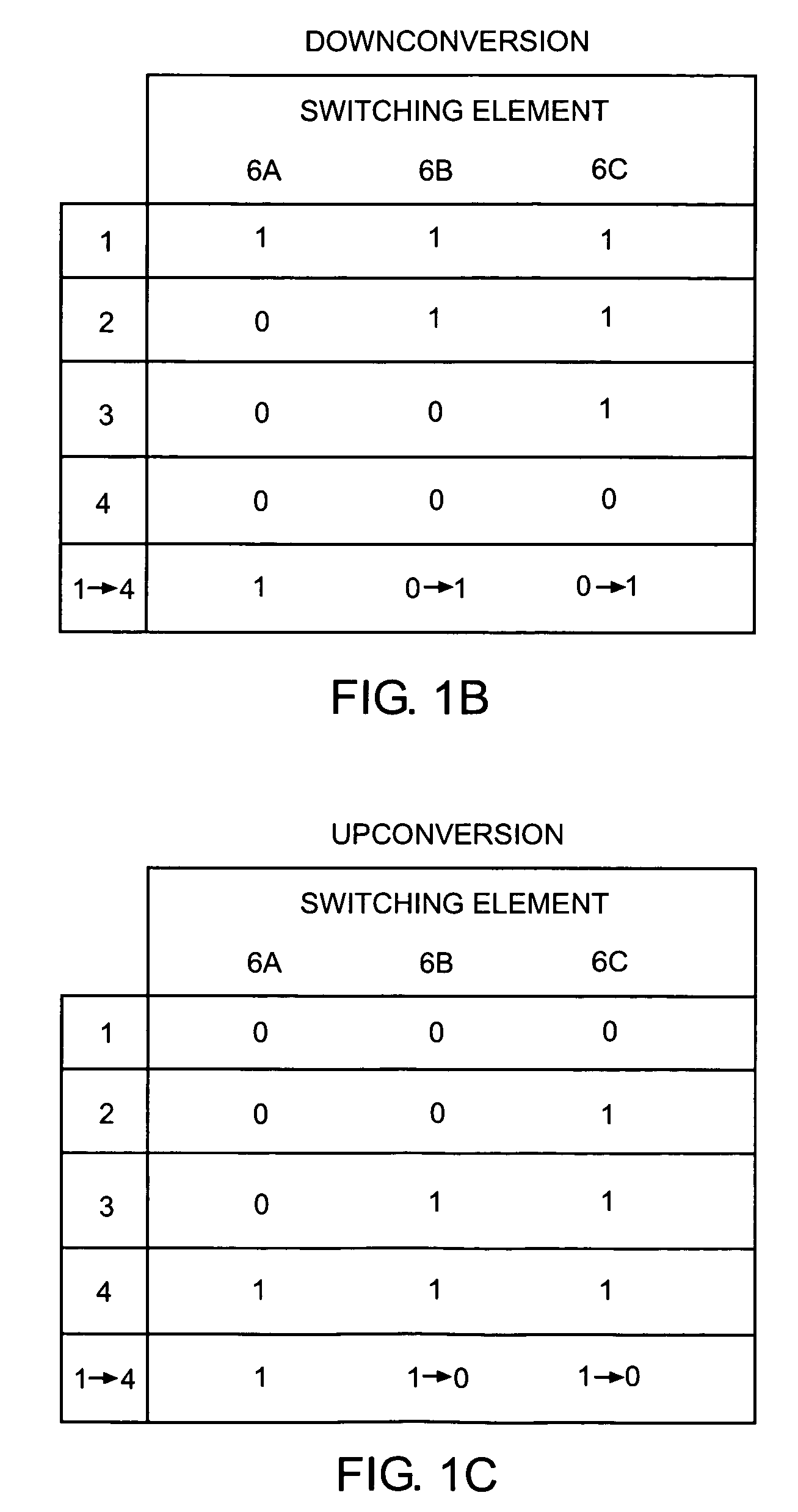
[0024]As illustrated, a multi-port frequency coupler 2, such as a circulator, is associated with a delay line 4 having a defined electrical length. The delay line 4 is divided into a number of sections, and in the present example is divided into three sections, wherein nodes defining the boundaries of each section are selectively coupled to ground through a corresponding switc...

second embodiment

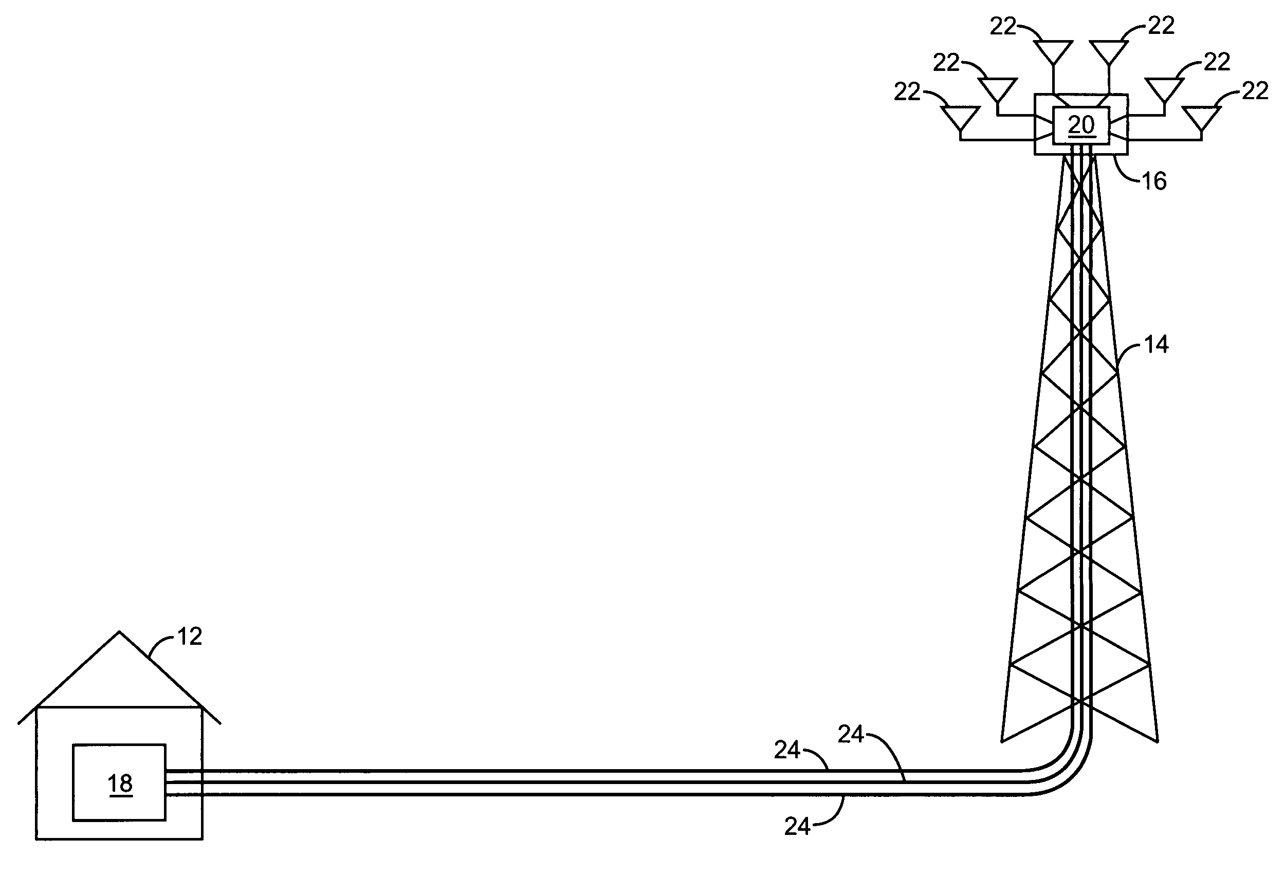
[0048]Turning now to FIG. 7, the cabling reduction system is illustrated. In this embodiment, the main receive signal is not translated, while the diversity receive signal is translated. Thus, the main receive signal and a translated diversity receive signal are combined in the masthead electronics 20 and sent over the feeder cable 24 to the base housing electronics 18. In particular, the main receive signal is received at main antenna 22M, and forwarded to combining circuitry 40 via the duplexer 28, and through an LNA 30. The diversity receive signal is received at diversity antenna 22D, filtered by the filter 34, amplified by the LNA 36, and translated from the first center frequency fC1 to a second center frequency fC2 by the diversity frequency translation circuitry 38. The main receive signal and the translated diversity receive signal are combined by combining circuitry 40 and sent to duplexer 26 for delivery to the base housing electronics 18 over the feeder cable 24. Upon re...


PUM


Abstract

The present invention provides a serrodyne architecture that is capable of operating at high frequencies. The architecture generally includes a coupler, a delay line, and a switching system. The delay line is coupled to a reflective port of the coupler. The switching system is coupled to the delay line at different points and is configured to selectively shunt those points on the delay line to change the effective electrical length of the delay line. The effective electrical length is changed throughout the period, corresponding to the amount the frequency of the input signal is shifted. In operation, an input signal is provided to an input port of the coupler, and an output signal is provided at the output port, wherein the input signal and the output signal vary by a translation frequency, which is controlled based on how the effective electrical length of the delay line is changed.

Description

[0001]This application claims the benefit of U.S. provisional application Ser. No. 60 / 579,869 filed Jun. 15, 2004, the disclosure of which is hereby incorporated by reference in its entirety.CROSS-REFERENCE TO RELATED APPLICATIONS[0002]The present invention is related to co-assigned U.S. patent application Ser. No. 10 / 811,164 filed Mar. 26, 2004 entitled FEEDER CABLE REDUCTION, the disclosure of which is incorporated herein by reference in its entirety.FIELD OF THE INVENTION[0003]The present invention relates to radio frequency communications, and in particular to translating signals received at one frequency to being centered about another frequency.BACKGROUND OF THE INVENTION[0004]In many communication technologies, there is a need to shift signals from one frequency to another. Such frequency translation often employs various types of mixers. Unfortunately, the inherent nature of mixing results in signals with a double sideband, which requires additional filtering or wastes avail...

Claims


Application Information

Patent Timeline
IPC IPC(8): H04M1/00H04B7/00
CPCH03D7/12
Inventor NICHOLLS, CHARLESBEAUDIN, STEVEBADIERE, DANIELBERGSMA, ADRIAN J.WILLETTS, MARK N.
Owner APPLE INC
Why Eureka
Try Eureka