System and method for cooling a compressor motor

a compressor motor and cooling system technology, applied in the field of system and method for improving the can solve the problems of sacrificing energy efficiency, difficult design of gas compression system, and difficulty in motor cooling of compressor motors in refrigeration systems, especially large-capacity systems, so as to improve the cooling of motors, improve the cooling effect, and improve the cooling effect of motors

Active Publication Date: 2007-02-27
JOHNSON CONTROLS TYCO IP HLDG LLP
View PDF17 Cites 59 Cited by
  • Summary
  • Abstract
  • Description
  • Claims
  • Application Information

AI Technical Summary

Benefits of technology

[0019]One advantage of the invention includes improvement in motor cooling in large capacity refrigeration systems without unacceptable compromises to system efficiency. Another advantage is excellent motor cooling through the combination of refrigerant gas circulation through the motor housing that can be further improved with circulation of liquid coolant through jackets or chambers located adjacent to targeted areas of the motor.

Problems solved by technology

Providing adequate motor cooling, without sacrificing energy efficiency of the compression system, continues to challenge designers of gas compression systems.
For example, motor cooling of compressor motors in refrigeration systems, especially large-capacity systems, remains challenging.
While this configuration reduces the risk of refrigerant leaks, it does not permit direct cooling of the motor using ambient air.
Unfortunately, the high velocity liquid refrigerant sprays produced by known direct liquid refrigerant injection techniques represent a potentially dangerous source of erosion to exposed motor parts such as the exposed end coils of the stator winding.
Such systems avoid the potential erosion problems of direct liquid refrigerant injection, but are not very effective in cooling other motor areas such as the air gap, rotor area, and the motor windings.
A significant drawback of the above gas-phase motor cooling systems and methods is that usually, virtually the entire refrigerant gas flow is circulated through the motor and motor housing.
There is much more refrigerant gas flowing through the motor than what is needed for cooling, and the gas flow through the motor generates substantial pressure drops that reduce the system efficiency.
While such pressure drops and resulting inefficiencies may be acceptable for small capacity refrigerant systems, they are not acceptable or suitable for large capacity compressors.
Another problem is the sourcing of the coldest available refrigerant gas through the motor housing to ensure adequate cooling.
However, a relatively high gas flow is required because the relatively high gas temperature cannot provide efficient cooling of the motor.
Also, the sourced gas must be re-compressed without providing any cooling effect in the cycle.
Thus, the high-pressure side is a poor motor coolant source because of its severe effects on system efficiency.
While the problem of marginal motor cooling due to elevated gas temperature is still encountered, the required volume of gas flow is lower because of the lower relative gas temperature.
Medium-pressure cooling systems, as described by U.S. Pat. No. 4,899,555, as well as by U.S. Pat. No. 6,450,781, have been implemented with limited success.
In both of the medium-pressure gas cooling systems, the gas circulated through the motor housing is at medium pressure, resulting in higher gas friction than if the gas were taken at low pressure, further limiting the cooling effect on the motor.

Method used


Image

  • System and method for cooling a compressor motor
  • System and method for cooling a compressor motor
  • System and method for cooling a compressor motor

Examples


Embodiment Construction

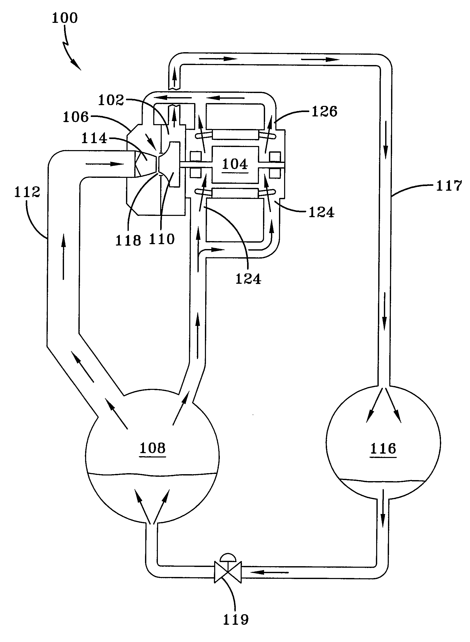
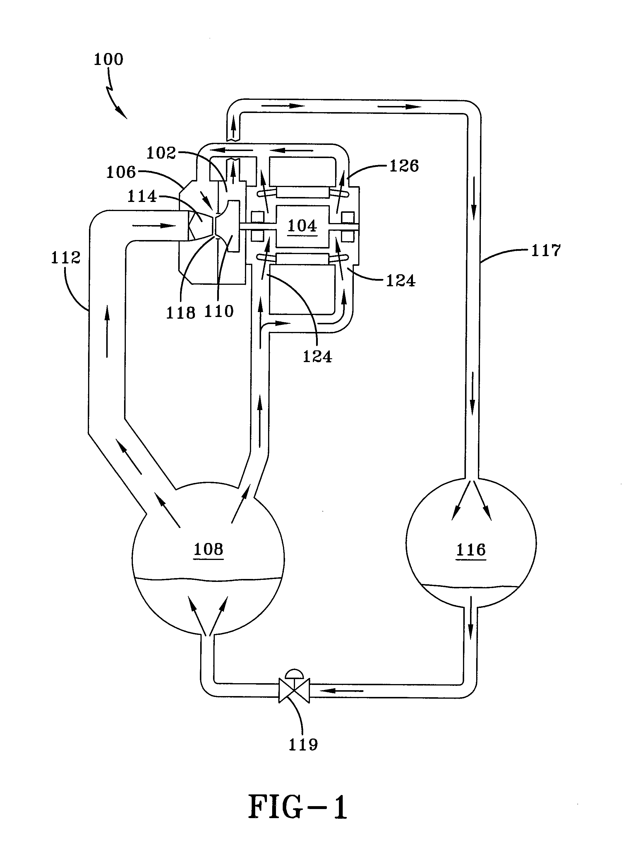
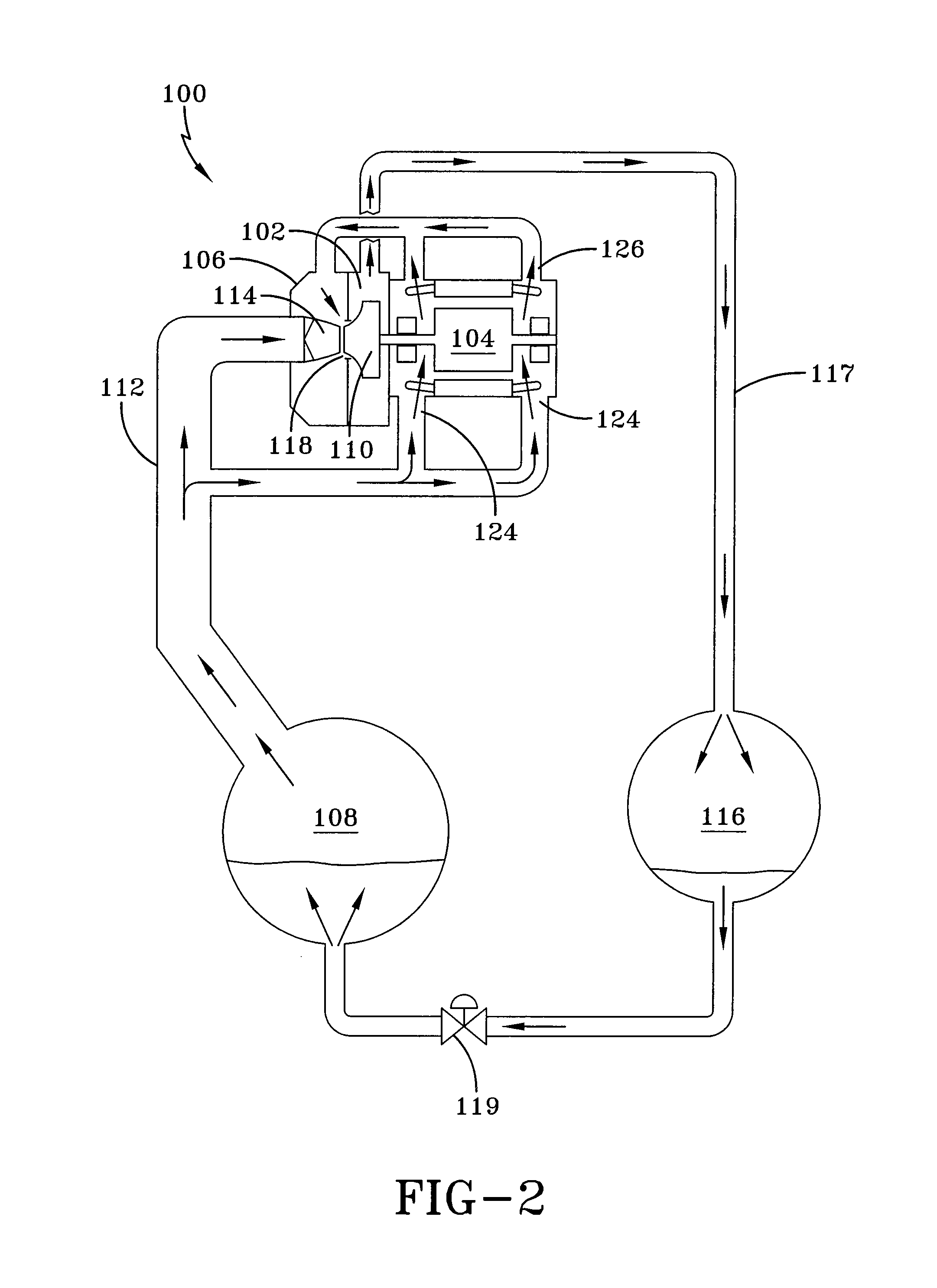
[0029]The invention provides optimized cooling of hermetic motors using low-pressure gas, such as uncompressed gas. The invention provides motor cooling by a gas sweep, with the gas source located in the low-pressure side of the compression circuit. In a refrigeration circuit application, the uncompressed refrigerant gas is preferably sourced from the evaporator, and is drawn into the motor housing, through or around the motor (or both), by a pressure reduction created at the suction inlet to the compressor. Alternatively, the refrigerant gas source is the suction pipe or a suction liquid trap.

[0030]The invention can provide for additional motor cooling by circulation of liquid coolant through a motor cooling jacket or through chambers provided in the motor housing. In refrigeration system embodiments, the circulating liquid can be liquid refrigerant, which liquid refrigerant can be injected directly into the motor housing, and any combination of these features can supplement the co...


PUM


Abstract

Apparatus and methods are provided for cooling motors used to drive gas and air compressors. In particular, the cooling of hermetic and semi-hermetic motors is accomplished by a gas sweep using a gas source located in the low-pressure side of a gas compression circuit. The gas sweep is provided by the creation of a pressure reduction at the compressor inlet sufficient to draw uncompressed gas through a motor housing, across the motor, and out of the housing for return to the suction assembly. The pressure reduction is created by means provided in the suction assembly, such as a nozzle and gap assembly, or alternatively a venturi, located upstream of the compressor inlet. Additional motor cooling can be provided by circulating liquid or another cooling fluid through a cooling jacket in the motor housing portion adjacent the motor.

Description

FIELD OF THE INVENTION[0001]This invention relates to systems and methods for improved cooling of motors used to drive compressors, such as air compressors and compressors used in refrigeration systems. In particular, the invention relates to cooling of compressor motors by uncompressed gas passing through the motor housing. The pressure reduction necessary to draw the uncompressed gas through the motor housing is generated by pressure reduction means, such as a nozzle and gap, or alternatively a venturi, provided in the suction assembly to the compression mechanism of the compressor.BACKGROUND OF THE INVENTION[0002]Gas compression systems are used in a wide variety of applications, including air compression for powering tools, gas compression for storage and transport of gas, and compression of refrigerant gases for refrigeration systems. In each system, motors are provided for driving the compression mechanism to compress the gas. The size and type of motor depends upon several fa...

Claims


Application Information

Patent Timeline
Patent Type & Authority Patents(United States)
IPC IPC(8): F25B3/00F25B1/04F25B31/00F25B39/04
CPCF04D25/06F04D25/082F04D29/4213F25B31/006F04D29/584F25B2341/0011F25B1/04F04D29/5806
Inventor DE LARMINAT, PAUL MARIE
Owner JOHNSON CONTROLS TYCO IP HLDG LLP
Why Eureka
Try Eureka